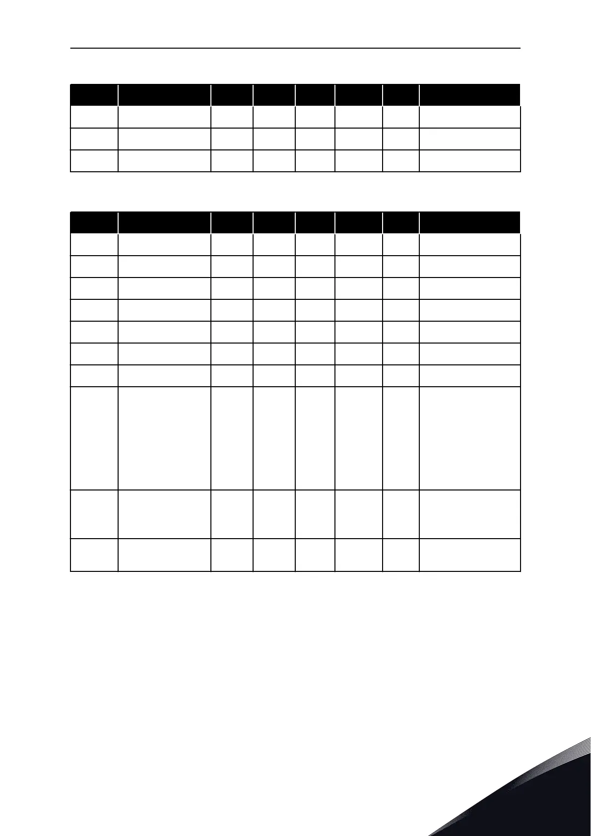
Table 9: M1 Quick Setup
Index Parameter Min Max Unit Default ID Description
1.28 RO2 Function 0 51 3 1104 See P3.5.3.2.1
1.29 RO3 Function 0 51 1 1107 See P3.5.3.2.1
1.30 AO1 Function 0 31 2 10050 See P3.5.4.1.1
Table 10: M1.33 Multi-step speed
Index Parameter Min Max Unit Default ID Description
1.33.1 Preset Frequency 1 P1.3 P1.4 Hz 10.0 105
1.33.2 Preset Frequency 2 P1.3 P1.4 Hz 15.0 106
1.33.3 Preset Frequency 3 P1.3 P1.4 Hz 20.0 126
1.33.4 Preset Frequency 4 P1.3 P1.4 Hz 25.0 127
1.33.5 Preset Frequency 5 P1.3 P1.4 Hz 30.0 128
1.33.6 Preset Frequency 6 P1.3 P1.4 Hz 40.0 129
1.33.7 Preset Frequency 7 P1.3 P1.4 Hz 50.0 130
1.33.8
Preset Frequency
Mode
0 1 0 128
0 = Binary Coded
1 = Number of inputs.
Preset frequency is
selected according to
how many of preset
speed digital inputs
are active.
1.33.9
External Fault
(Close)
DigIN
SlotA.3
405
FALSE = OK
TRUE = External fault
1.33.10 Fault Reset (Close)
DigIN
Slot0.1
414
Resets all active faults
when TRUE
1.4.4 PID CONTROL APPLICATION
You can use the PID control application with processes where you control the process
variable (for example pressure) through control of the speed of the motor.
In this application, the internal PID controller of the drive is configured for 1 setpoint and 1
feedback signal.
It is possible to use 2 control places. Make the selection of the control place A or B with DI6.
When control place A is active, the start/stop commands are given by DI1, and the PID
controller gives the frequency reference. When control place B is active, start/stop
commands are given by DI4, and AI1 gives the frequency reference.
QUICK STARTUP GUIDE VACON · 35
24-HOUR SUPPORT +358 (0)201 212 575 · EMAIL: VACON@VACON.COM
1

 Loading...


