4.1.4 I/O
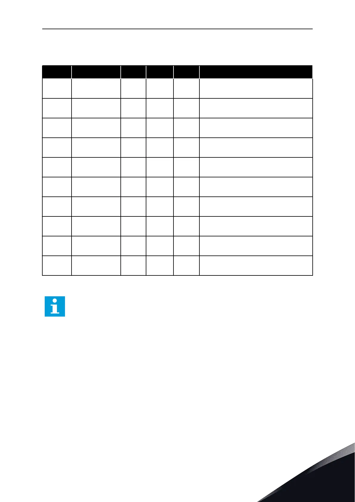
Table 22: I/O signal monitoring
Index Monitoring value Unit Scale ID Description
V2.4.1 Slot A DIN 1, 2, 3 1 15
Shows the status of the digital inputs 1-3 in
slot A (standard I/O)
V2.4.2 Slot A DIN 4, 5, 6 1 16
Shows the status of the digital inputs 4-6 in
slot A (standard I/O)
V2.4.3 Slot B RO 1, 2, 3 1 17
Shows the status of the relay inputs 1-3 in
slot B
V2.4.4 Analogue input 1 % 0.01 59
The input signal as a percentage of the used
range. Slot A.1 as default.
V2.4.5 Analogue input 2 % 0.01 60
The input signal as a percentage of the used
range. Slot A.2 as default.
V2.4.6 Analogue input 3 % 0.01 61
The input signal as a percentage of the used
range. Slot D.1 as default.
V2.4.7 Analogue input 4 % 0.01 62
The input signal as a percentage of the used
range. Slot D.2 as default.
V2.4.8 Analogue input 5 % 0.01 75
The input signal as a percentage of the used
range. Slot E.1 as default.
V2.4.9 Analogue input 6 % 0.01 76
The input signal as a percentage of the used
range. Slot E.2 as default.
V2.4.10 Slot A AO1 % 0.01 81
The analogue output signal as a percentage
of the used range. Slot A (standard I/O)
4.1.5 TEMPERATURE INPUTS
NOTE!
This parameter group is visible when you have an option board for temperature
measurement (OPT-BH).
MONITORING MENU VACON · 103
24-HOUR SUPPORT +358 (0)201 212 575 · EMAIL: VACON@VACON.COM
4

 Loading...


