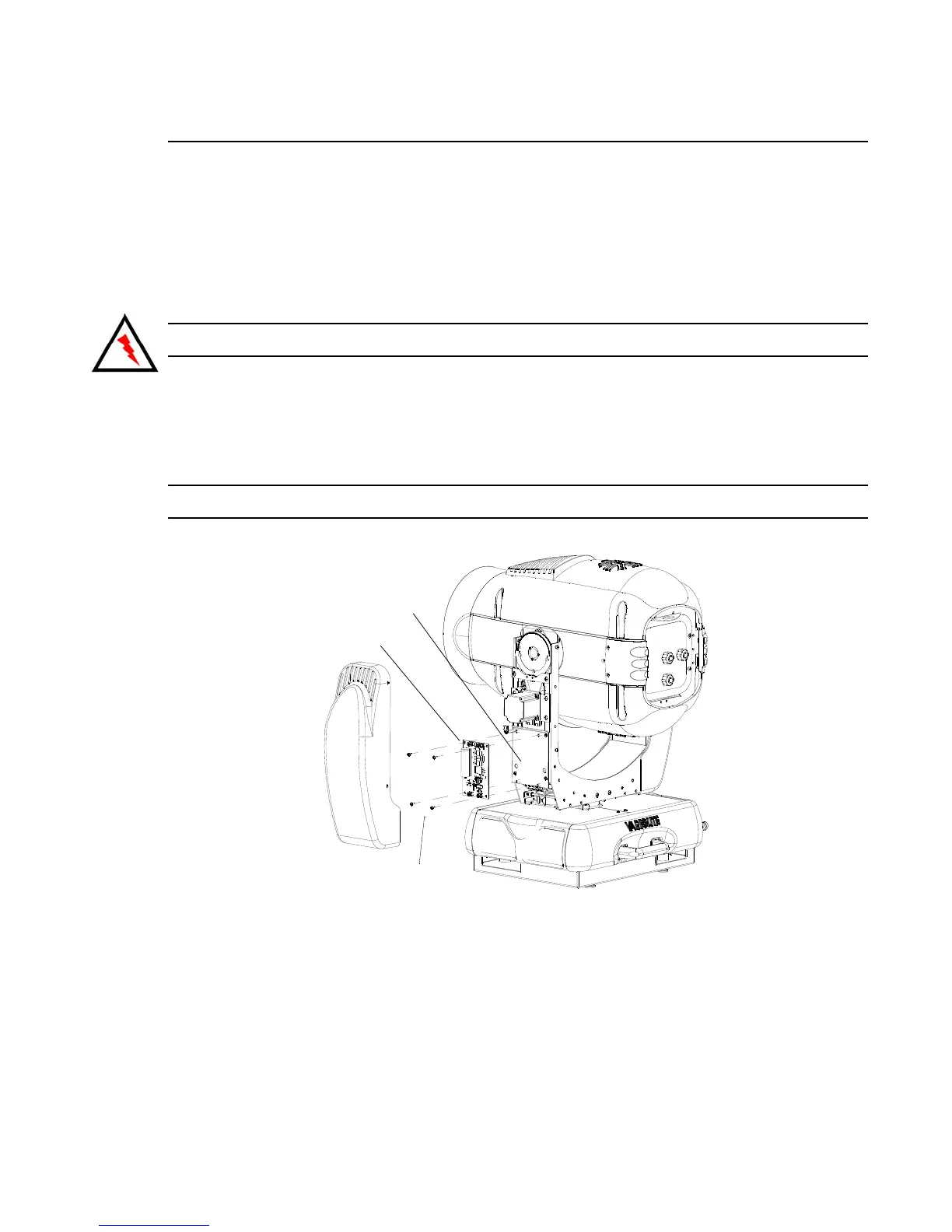
MAINTENANCE PROCEDURES : IGNITOR BOARD REPLACEMENT
02.9686.0010 0 35
2
Ignitor Board Replacement
VL Part No: 24.9661.3126
Repair Procedure
Step 1. Disconnect luminaire AC input cable from power source.
Step 2. At tilt-side leg, remove yoke leg cover by removing four 6-32 x 5/16" screws.
CAUTION: Always use anti-static precautions when working with PCBs.
Step 3. Disconnect ignitor PCB wires by removing four screws that secure wire ring terminals to
PCB and remove ignitor PCB.
Step 4. Remove four 6-32 x 3/8" screws and remove ignitor PCB.
Step 5. Replace by performing steps 2 through 4 in reverse.
Note: Make sure and orient ignitor properly (as shown in Figure 2-11).
Figure 2-11: Ignitor Board Replacement
Ignitor Board
Mounting Plate
Remove Ignitor Board
Mounting Screws