Chapter 6 Installation and Initial Operation Alpha Compact 32708612
Version: 14.12.2012 page 72 of 135
Requirements
- Labeler is turned on
- No transportation of products
Required equipment:
- Screw driver G00
- Screw wrenchs 14 and 12
Instructions
Please adjust the air assist as follows
Step Procedure
1
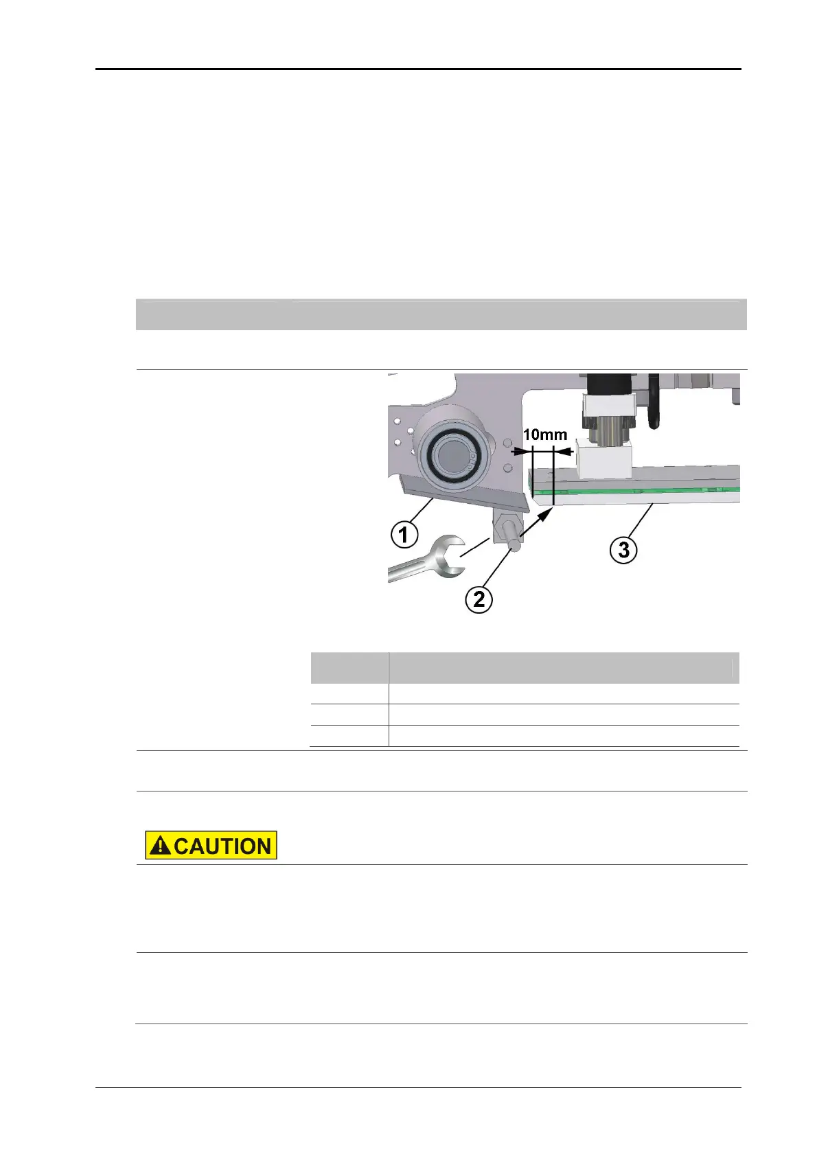
Check firstly if the air assist beams hits appr. 10 mm behind the leading
edge of the tamp (see Fig.: 6-29).
Fig.: 6-29: Air assist unit (side view)
No. Description
1
PEELER BLADE
2
AIR ASSIST TUBE
3
TAMP PAD
2
If an adjustment is necessary, the counter nut has to be unscrewed and
the tube has to be turned into position and then arrest the nut again.
3
Following adjustment can only be arranged during a label feed and re-
quired a lot of experience.
DANGER OF BEING CRUSHED IN! Keep away from tamp.
4
Push the [ENTER]-button of the printer in order to feed a label.
Regulate in the meantime the air beam by the flow control valve at the
bottom side of the stainless steel cabinet (see p. 71).
- turning clockwise leads to a weakening.
- turning counter clockwise leads to an amplification of the air jet.
5
Repeat step 4 until the label is pushed safely against the tamp pad.
Search for an adjustment requiring only a little quantity of air pressure.
You will thus reduce the air pressure consumption and you will reduce
possible air rotations.