Chapter 6 Installation and Initial Operation Alpha Compact 32708612
Version: 14.12.2012 page 69 of 135
Settings coupling rewinder
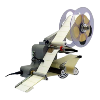
Fig.: 6-27: Adjustment coupling
No. Description
1
DIRECTION OF ADJUSTMENT
2
DANCER ARM
3
CORE
4
ADJUSTMENT SCREW
5
CYLINDER BOLT
6
SETSCREW (FIXING)
7
AXIS TO COUPLING
Danger of damage.
The rewinder has a free-wheeling that impedes the unwinding of
the liner material. By violent turning against the rewinding direc-
tion, it can be damaged. Never turn the rewinder against the re-
winding direction. Do no push the dancer arm by force over its
end position.
The coupling to the rewinder is aligned when the system is delivered. To avoid dam-
ages of the dancer arm due to overload, the dancer arm adjusts itself at inappropriate
force.
Requirements
Label web is not inserted.
Product transportation is stopped.
Labeler is turned off.
Required equipment
2,5mm and 3mm hexagon socket wrench
Instructions