Chapter 6 Installation and Initial Operation Alpha Compact 32708612
Version: 14.12.2012 page 49 of 135
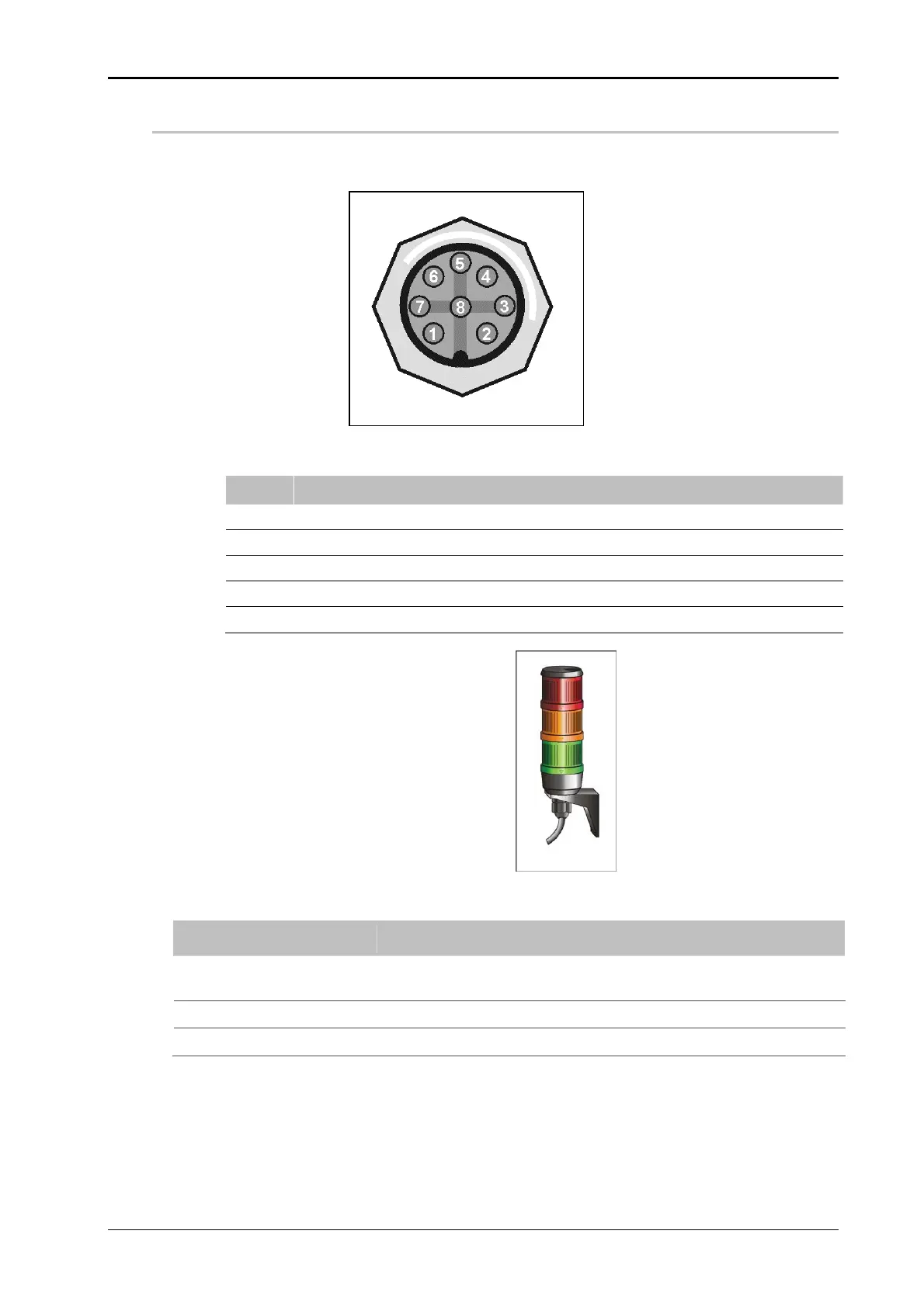
(X6) Alarm Lamp (Option)
The connection of an optional alarm lamp happens via M12, 8 pin plug.
Fig.: 6-8: Pin Assignment Alarm Lamp
PIN Assignment
1 + 24V DC RED LAMP
2 + 24V DC YELLOW LAMP
3 + 24V DC GREEN LAMP
4 NOT USED
5 GROUND (-)
Fig.: 6-9 Alarm Lamp
Lamp Description
Red (permanent light)
Flashes in case of system failure / error (READY-Signal is re-
set). Possible cause: label out or labeler error.
Yellow (permanent light)
Low Label Warning
Green (permanent light)
System ready (Ready Signal is set)