Chapter 6 Installation and Initial Operation Alpha Compact 32708612
Version: 14.12.2012 page 71 of 135
*²Air assist setup-with optional applicator
Danger due to actively controlled movements.
DANGER OF BEING CRUSHED!
The movements of the applicator are driven by pneumatic cylin-
ders.
- Maintain a distance from applicator.
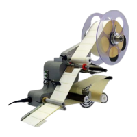
For the label application the label must be pressed against the Tamp Pad until it is cap-
tured by the vacuum. This is arranged by the air jet of the air assist unit.
The air assist unit consists of an air assist tube (5) with three holes and one flow control
valve (Pos.1), that may set the effusing air.
Fig.: 6-28: Air assist unit at applicator
No. Description
1
FLOW CONTROL VALVE (AIR ASSIST)
2
PEELER BLADE
3
AIR ASSIST TUBE
4
TAMP PAD
*² only if system has the appropriate feature.