Maintenance
3103−1/A1
Winterthur Gas & Diesel Ltd.
3/ 3
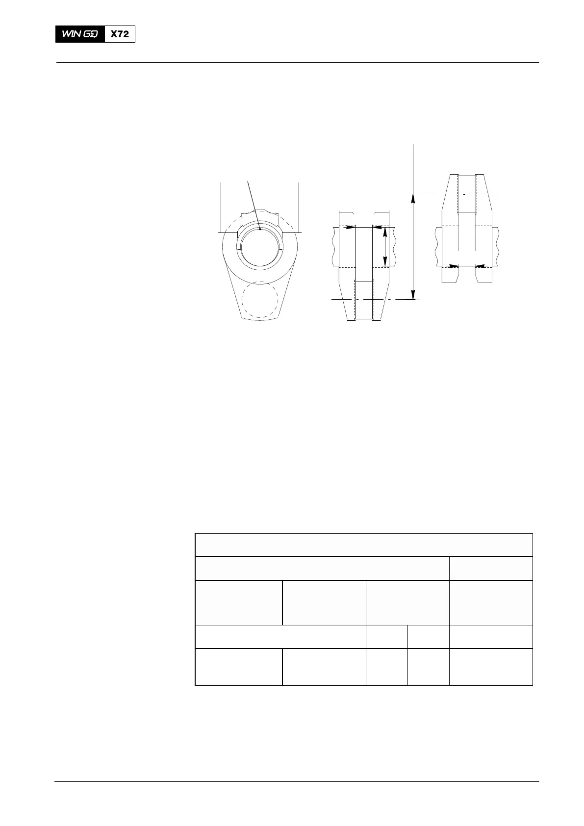
4. Calculate
STROKE
D
94305
nBDC
nTDC
Fig. 3
The difference between the values shown shows the crank deflection during one full
turn of the crankshaft (Fig. 2).
Where values are measured that are more than the maximum permitted limits, the
cause must be found. The necessary procedures must then be done to repair the
problem (defective main bearing, engine stay changed because of hull deformation,
loose hold-down bolts, defective propeller shaft bearings or equipment 94305, etc.).
The limits are applicable for all conditions of ship service after delivery, i.e.:
D The draught and trim are in the limits for usual operation.
D The engine is stopped and is hot or cold.
D If the engine is in a cold condition the tank heating (which is close to or below the
main engine and the pre-heater of the main lubricating oil separator) must not be
in operation for a minimum of eight hours before the procedure given in
paragraph 2.
Usual Operation: Crank-web Deflection Limits (mm)
Vertical Horizontal
Cylinder No. 1
(Driving end)
Cylinder No. 2
to next to last
cylinder
Last cylinder
(Free end)
All cylinders
Note
1) Note
2)
0.82
−0.82
0.58
−0.58
0.58
−0.58
0.58
−0.82
0.27
−0.27
1) For engines without torsional vibration damper, or front disc or free end PTO.
2) For engines with torsional vibration damper or front disc or free end PTO.
Speak to WinGD, if the final indications are more than the limits given in the table
above.
2015
Measuring Crank Deflection

 Loading...


