Maintenance4103−2/A1
Winterthur Gas & Diesel Ltd.
4/ 6
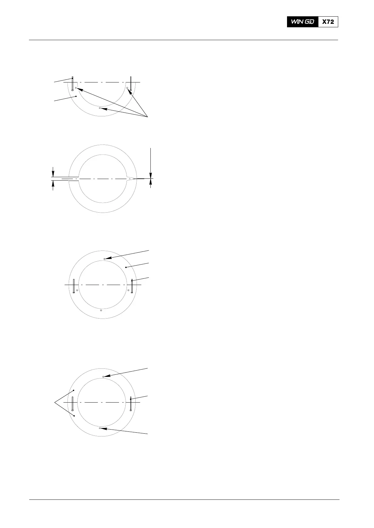
5) Put three flange screws (6, Fig. 4) in
position as shown in the wheel half (1).
Tighten the screws temporarily.
6) Turn the turn the crankshaft to move
the gear wheel half (1, Fig. 5) to the
bottom position.
7) Put the other half of the crankshaft gear
wheel (1, Fig. 6) (with the other two
assembled elastic studs) in position on
the crankshaft flange. Make sure that at
one side, there is no clearance.
8) Measure the clearance between the
two halves of the crankshaft gear
wheel. The clearance must be between
0.16 mm to 041 mm.
Note: If the clearance is not between
0.16 mm and 0.41 mm do not
assemble the gear wheel. Refer to
paragraph 2, step 5.
9) Adjust the top half of the crankshaft
gear wheel (1) to get an equal
clearance on each side.
10) Lightly tighten the castle nuts on the
elastic studs (3, Fig. 7).
11) Put a flange screw (6) in the center
position in the top half of the crankshaft
gear wheel (1). Temporarily tighten the
flange screw.
12) Remove the two outer flange screws
from the bottom half of the crankshaft
gear wheel (1). Make sure that only the
top and bottom flange screws (6,
Fig. 8) stay in position.
13) Make sure that there is no clearance on
the seating surfaces between the
crankshaft gear wheel and the
crankshaft flange.
14) Apply Molykote paste the threads of the
four remaining castle nuts (1, Fig. 3)
15) Install the four remaining castle nuts (1)
to the elastic studs (3).
Note: In step 16), tighten only the castle
nuts that have Molykote paste on
the threads.
16) Use the slugging wrench (94002−60) to
symmetrically tighten the castle nuts.
Use a wrench to hold the opposite
castle nuts (that have a split pin and
Loctite 262 on the threads).
2015
Replacing the Gear Wheel on the Crankshaft
6
3
1
6
3
6
1
Fig. 5
Fig. 6
Fig. 7
Fig. 8
WCH02403
WCH02403
WCH02403
WCH02403
0.16 mm to
0.41 mm
Clearance
0.00 mm
6
1
3

 Loading...


