06/2014
4-101
WC 5022/5024
Repairs and Asdjustments
Version 1.0
ADJ 18.1.2 IOT Lead Edge/Side Edge Registration
Purpose
To align the image on the drum with the proper position (Lead/Side Edge) of the paper.
Check
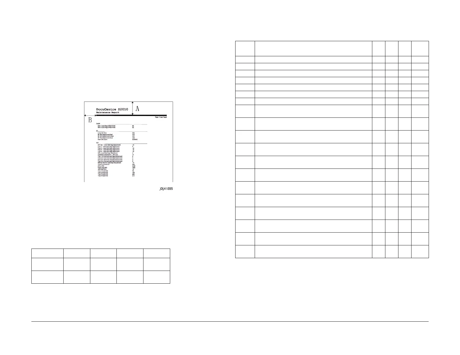
1. Load A4 paper into the Tray in SEF orientation.
2. Enter the CE Mode and input 999-980 (Maintenance Report) in the Chain-Link.
3. Pressing <Start> prints the Maintenance Report.
4. Measure the Lead and Side Edges of the print pattern.
• Lead Edge: Part A of the pattern
• Side Edge: Part B of the pattern
Figure 1 j0lj41895
5. Check that the measured values of the Lead Edge (A) and Side Edge (B) fall within the
corresponding specifications.
NOTE: To perform measurement for the Lead Edge (A) and Side Edge (B) of Duplex
printouts, load the Maintenance Report that was output on the Platen, and make a 1 -> 2
Sided copy to perform the measurement.
Adjustment
1. Enter the CE Mode.
2. Adjust the NVM until each measured value of the Lead Edge (A) and Side Edge (B) fall
within the specifications of the corresponding mode.
• If the measured value is short: Set a larger value.
• If the measured value is long: Set a smaller value.
3. After adjustment, print the Maintenance Report in the same mode again.
4. Repeat the procedure until the measured values of the Lead Edge (A) and Side Edge (B)
fall within the specifications.
Table 1 IOT Lead Edge/Side Edge
Item Simplex Duplex MSI STM (TTM)
Lead Edge
(A)
30 +/-2.4
mm
30 +/-3.4
mm
30 +/-3.1
mm
30 +/-3.1
mm
Side Edge (B) 30 +/-3.0
mm
30 +/-3.4
mm
30 +/-3.2
mm
30 +/-3.0
mm
Table 2 NVM List
Chain-
Link Name Min
Initi
al Max Step
742-001 PH_LEAD_REGI_ALL_TRAY -50 0 50 2 ms
742-002 PH_LEAD_REGI_TRAY1 -50 0 50 2 ms
742-003 PH_LEAD_REGI_TRAY2 -50 0 50 2 ms
742-004 PH_LEAD_REGI_TRAY3 -50 0 50 2 ms
742-005 PH_LEAD_REGI_TRAY4 -50 0 50 2 ms
742-006 PH_LEAD_REGI_MSI -50 0 50 2 ms
742-007 PH_LEAD_REGI_DUPLEX -50 0 50 2 ms
749-001 ROS_LASER_SIDE_REGI_ADJUSTMENT_ALL_TRAY -50 0 50 0.254
mm
749-002 ROS_LASER_SIDE_REGI_ADJUSTMENT_TRAY 1 -50 0 50 0.254
mm
749-003 ROS_LASER_SIDE_REGI_ADJUSTMENT_TRAY 2 -49 0 49 0.254
mm
749-004 ROS_LASER_SIDE_REGI_ADJUSTMENT_TRAY 3 -49 0 49 0.254
mm
749-005 ROS_LASER_SIDE_REGI_ADJUSTMENT_TRAY 4 -49 0 49 0.254
mm
749-006 ROS_LASER_SIDE_REGI_ADJUSTMENT_MSI -50 0 50 0.254
mm
749-007 ROS_LASER_SIDE_REGI_ADJUSTMENT_DUP_ALL_
TRAY
-50 0 50 0.254
mm
749-008 ROS_LASER_SIDE_REGI_ADJUSTMENT_DUP_TRA
Y 1
-50 0 50 0.254
mm
749-009 ROS_LASER_SIDE_REGI_ADJUSTMENT_DUP_TRA
Y 2
-50 0 50 0.254
mm
749-010 ROS_LASER_SIDE_REGI_ADJUSTMENT_DUP_TRA
Y 3
-50 0 50 0.254
mm
749-011 ROS_LASER_SIDE_REGI_ADJUSTMENT_DUP_TRA
Y 4
-50 0 50 0.254
mm
749-012 ROS_LASER_SIDE_REGI_ADJUSTMENT_DUP_MSI -50 0 50 0.254
mm
 Loading...