4.7 Dimensional Drawings of Base-mounted SERVOPACK Model
4-31
4
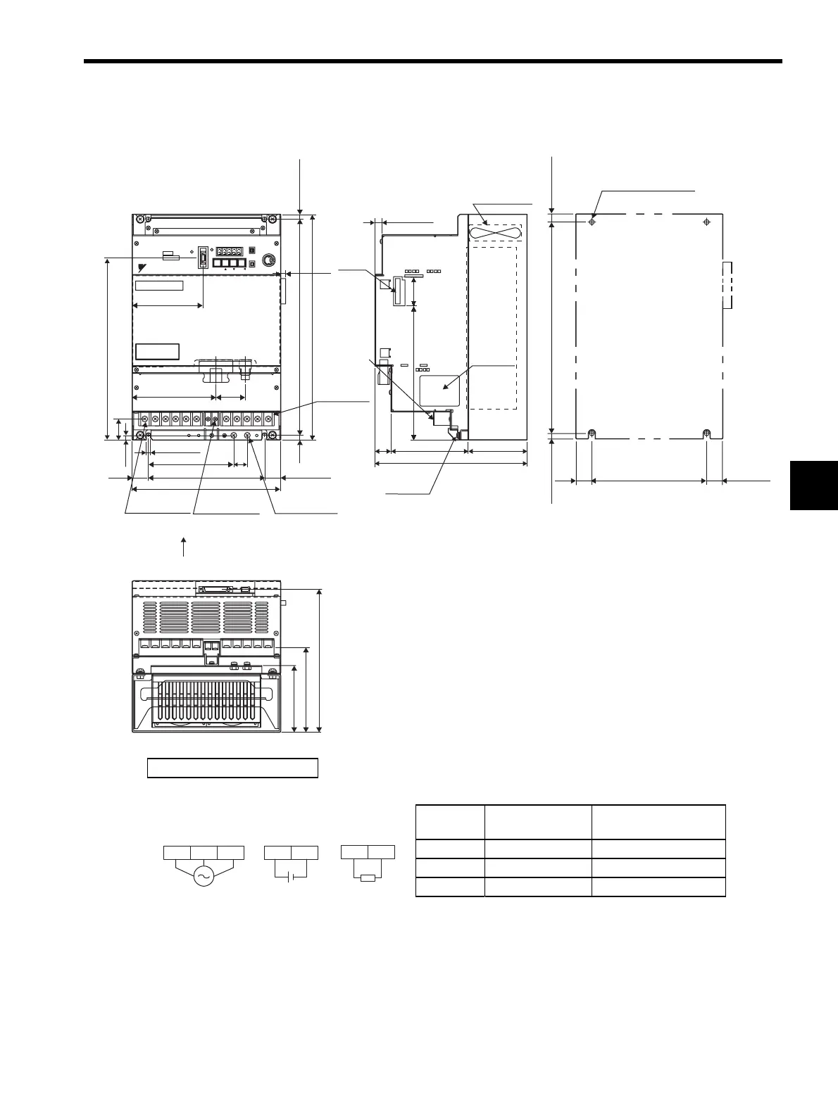
4.7.8 Three-phase 400 V: 6.0 kW/7.5 kW (60DE/75DE)
Cooling fan
10 (0.39)
39
(1.54)
24
(0.94)
121 (4.76)
90 (3.54)
235 (9.25)
Main circuit/
Control circuit
terminal
CN10
L1 L2 L3 +1 +2 - 24V 0V B1 B2 U V W
MODE/SET
DATA/
CN3 CN8
BATTERY
CHARGE
POWER
CN1
CN2
SERVOPACK 200V
SGDH-
1AAE
Ver.
YASKAWA
335 (13.19)
7.5
(0.30)
7.5 (0.30)
350 (13.78)
46
(1.81)
8 (0.31)
7 (0.28)
32 (1.26)
283 (11.14)
7 (0.28)
158 (6.22)
20
(0.79)
25
(0.98)
180 (7.09)
230 (9.06)
104 (4.09)
133 (5.24)
222 (8.74)
CN5
110 (4.33)
130 (5.12)
211 (8.31)
(25) (0.98)
335 (13.19)
7.5 (0.30)
(7.5) (0.30)
180 (7.09)
25
(0.98)
(25) (0.98)
Main circuit
terminal M5
Main circuit
terminal M5
Control circuit
terminal
M4
Ground
terminal M5
Nameplate
Ground
terminal
Mounting Hole Diagram
4×M6 screw holes
A
View A
Units: mm (in)
Approx. mass: 13.5 kg (29.76 lb)
External Terminal Connector
SERVOPACK Connector
Connector
Symbol
SERVOPACK
Connector Model
Manufacturer
CN1 10250-52A2JL Sumitomo 3M Co., Ltd.
CN2 53460-0611 Molex Japan Co., Ltd.
CN3 10214-52A2JL Sumitomo 3M Co., Ltd.
24 VDC
24 V 0 V
L2 L3L1
B1 B2
External
regenerative
resistor
400 VAC
50/60 Hz
Three-phase
Main circuit
power supply
Control power
supply

 Loading...