2.6 Selecting Peripheral Devices
2-29
2
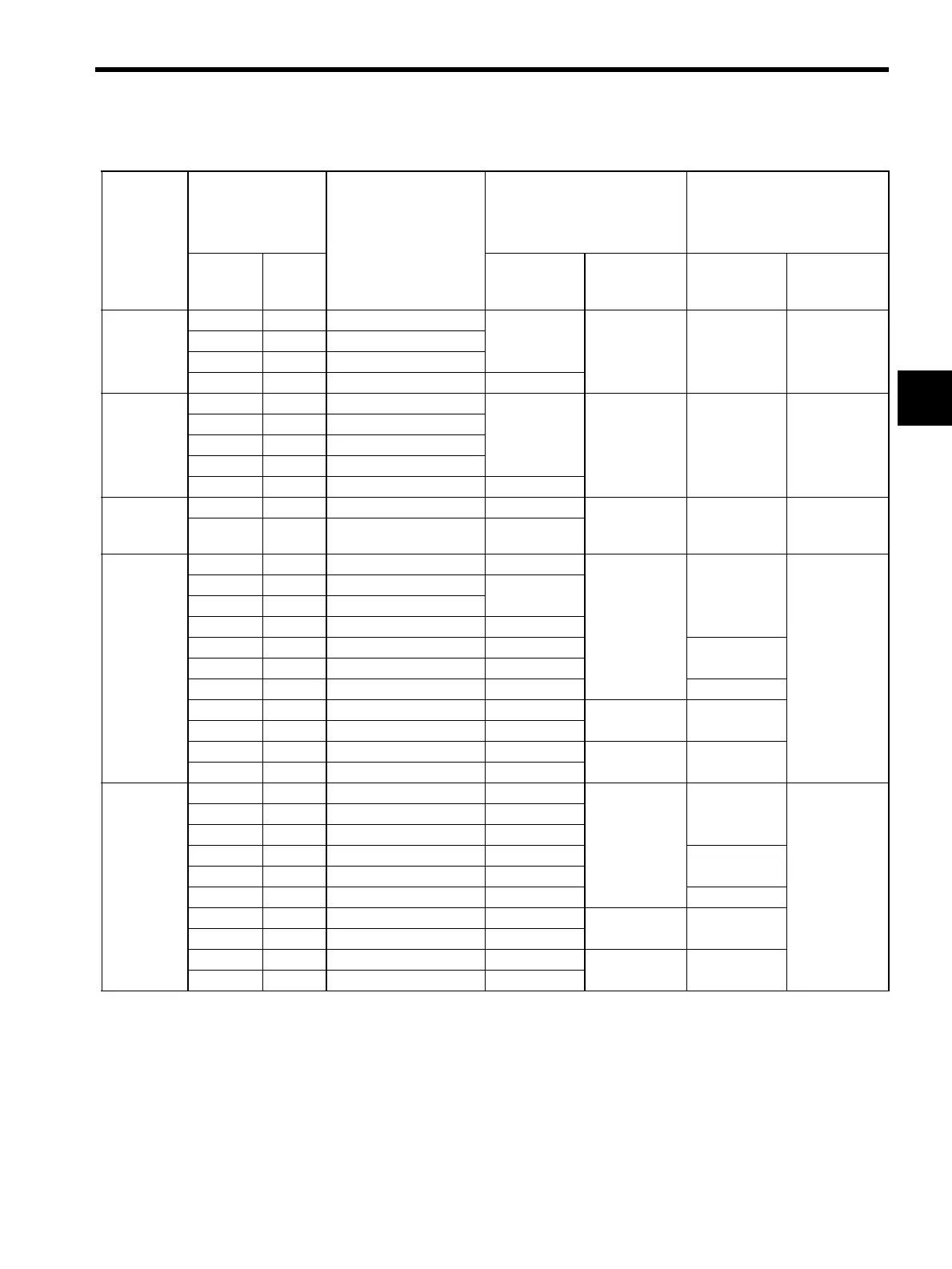
2.6.2 Molded-case Circuit Breaker and Fuse Capacity
* 1. Nominal value at the rated load. The specified derating is required to select an appropriate
fuse capacity.
* 2. Cutoff characteristics (25°C): 300% five seconds min. and inrush current of 20ms.
* 3. A preventive circuit for inrush current is not built in the 24 VDC control power supply. The
protective circuit must be designed by the customer.
* 4. Make sure the current capacity is accurate. For the SERVOPACK with the cooling fan built-
in, an inrush current flows; 200 % of the current capacity in the table above for two seconds,
when turning ON the control circuit power supply to start the fan working.
Note: Do not use a fast-acting fuse. Because the SERVOPACK’s power supply is a capacitor
input type, a fast-acting fuse may blow when the power is turned ON.
Main
Circuit
Power
Supply
SERVOPACK
Model
Power Supply
Capacity per
SERVOPACK
(kVA)
Current Capacity of the
Molded-case Circuit Breaker
and the Fuse (A
rms
)
∗1,∗2
(
Refer to 5.8.9
)
Inrush Current
Capacity
(kW)
SGDH-
Main Circuit
Power Supply
Control Cir-
cuit Power
Supply
Main Circuit
Power Supply
Control Cir-
cuit Power
Supply
Single-
phase
100 V
0.03 A3BE 0.15
4
0.26 32A 30A
0.05 A5BE 0.25
0.10 01BE 0.40
0.20 02BE 0.60 6
Single-
phase
200 V
0.03 A3AE 0.20
4
0.13 63A 60A
0.05 A5AE 0.25
0.10 01AE 0.40
0.20 02AE 0.75
0.40 04AE 1.2 8
Single-
phase
220 V
0.75 08AE-S 2.1 11
0.13
∗
4
130A 66A
1.50 15AE-S 4.0 19
Three-
phase
200 V
0.45 05AE 1.4 4
0.15
∗
4
118A
60A
0.75 08AE 1.9
7
1.0 10AE 2.3
1.5 15AE 3.2 10
2.0 20AE 4.3 13
63A
3.0 30AE 5.9 17
5.0 50AE 7.5 28 67A
6.0 60AE 12.5 32
0.27
∗
4
40A
7.5 75AE 15.5 41
11.0 1AAE 22.7 60
0.3
∗
4
80A
15.0 1EAE 30.9 81
Three-
phase
400 V
0.45 05DE 1.1 1.6
0.7
∗
4
10A
(
24 VDC
)
∗
3
1.0 10DE 2.3 3.4
1.5 15DE 3.2 4.6
2.0 20DE 4.9 7.1
20A
3.0 30DE 6.7 9.7
5.0 50DE 10.3 14.9 78A
6.0 60DE 12.4 17.8
1.2
∗
4
20A
7.5 75DE 15.4 22.3
11.0 1ADE 22.6 32.7
1.3
∗
4
40A
15.0 1EDE 30.9 44.6
 Loading...
