4.8 Dimensional Drawings of Rack-mounted SERVOPACK Model
4-37
4
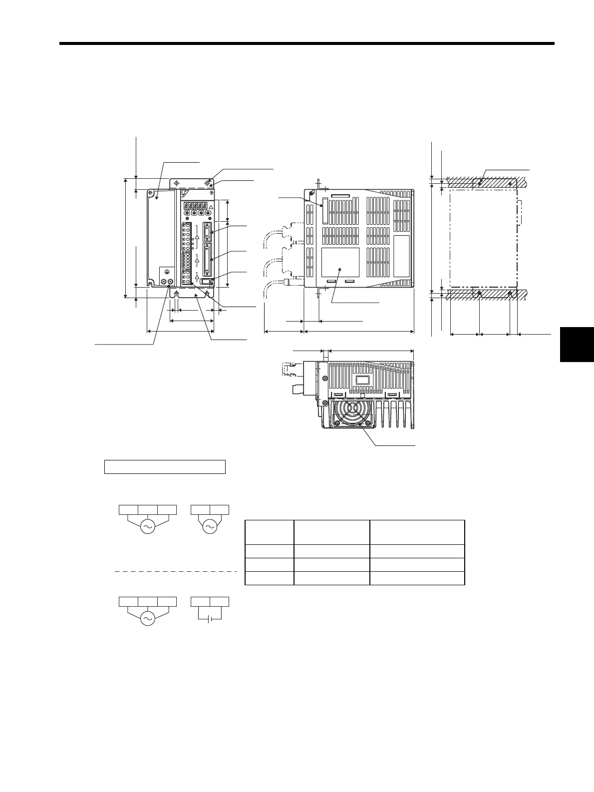
4.8.4 Three-phase 200 V: 1.5 kW (15AE-R)
Three-phase 400 V: 500 W/750 W/1.0 kW/1.5 kW (05DE-R/08DE-R/10DE-R/
15DE-R)
Cooling fan
Terminal
block
39 (1.54)
8
(0.31)
106 (4.17)
-
23D1
CN3
CN1
CN2
YASKAWA
YASKAWA
SERVOPACK
SGDH-
7 (0.28) 141.5 (5.57)
195 (7.68)
17.5 (0.69)
17.5 (0.69)
72 (2.83)
5 (0.20)
2×
φ
5 (φ0.20)
110 (4.33)
180 (7.09)(75) (2.95)
7.5 (0.30)
50±0.5
(1.97±0.02)
180 ± 0.5 (7.09 ± 0.02)
(7.5) (0.30)
(12) (0.47
(48)
(1.89)
24.5 (0.96)
CN10
6 (0.24)
6 (0.24)
Heat sink
Flange
Flange
Mounting Hole Diagram
Ground terminal
2×M4 screws
4×M4 screw
Nameplate
(Mounting pitch)
(Mounting pitch)
Units: mm (in)
Approx. mass: 3.0 kg (6.61 lb)
External Terminal Connector
SERVOPACK Connector
Connector
Symbol
SERVOPACK
Connector Model
Manufacturer
CN1 10250-52A2JL Sumitomo 3M Co., Ltd.
CN2 53460-0611 Molex Japan Co., Ltd.
CN3 10214-52A2JL Sumitomo 3M Co., Ltd.
L1C L2C
L2 L3L1
24 VDC
24 V 0 V
L2 L3L1
200 VAC
50/60 Hz
Three-phase
400 VAC
50/60 Hz
Three-phase
200 VAC
50/60 Hz
Single-phase
Main circuit
power supply
Control power
supply
Main circuit
power supply
Control power
supply