1.3 Examples of Servo System Configurations
1-9
1
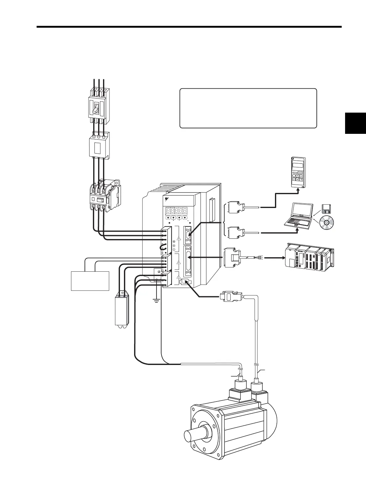
1.3.3 Three-phase, 400 V Main Circuit
∗2
∗1
∗3
Usea24VDCpowersupply.(Mustbepreparedbytheuser.)
BesuretodisconnecttheleadbetweenB2andB3,before
connectinganexternalregenerativeregistortothe
SERVOPACK.
ForconnectingaDCreactor,referto6.4.8DCReactorfor
HarmonicSuppression.
RST
L1
L2
L3
U
V
W
24V
0V
B1
B2
B3
1
2
C
N
3
C
N
1
C
N
2
MODE/SET
DATA/
CHARGE POWER
YASKAWA
SERVOPACK
SGD
H-
200V
+
−
DCpower
supply(24VDC)
Noisefilter
Molded-case
circuitbreaker
(MCCB)
Powersupply
Three-phase400VAC
Protectsthepowersupply
linebyshuttingthe
circuitOFFwhen
overcurrentis
detected.
(Referto5.8.9.)
Usedtoeliminate
externalnoisefromthe
powerline.
(Referto5.8.10.)
Magnetic
contactor
Turnstheservo
ONandOFF.
Installasurge
suppressor.
(Referto
5.8.11.)
Regenerative
resistor
Connectanexternal
regenerativeresistor
toterminalsB1andB2
iftheregenerative
capacityisinsufficient.
(Referto5.8.6.)
∗2
∗1
∗3
Servomotor
maincircuitcable
Encodercable
SGMH
Servomotor
(Referto5.1,5.2.)
(Referto5.4,5.5.)
Hostcontroller
I/Osignalcable
(Referto5.7.)
(Referto5.8.1.)
Connectioncable
forpersonalcomputer
SGDH-DE
SERVOPACK
Connectioncable
fordigitaloperator
Personalcomputer
(Referto5.8.2.)
Digital
operator
(Referto5.8.2.)