4.4 SERVOPACK’s Power Supply Capacities and Power Losses
4-17
4
4.4 SERVOPACK’s Power Supply Capacities and Power Losses
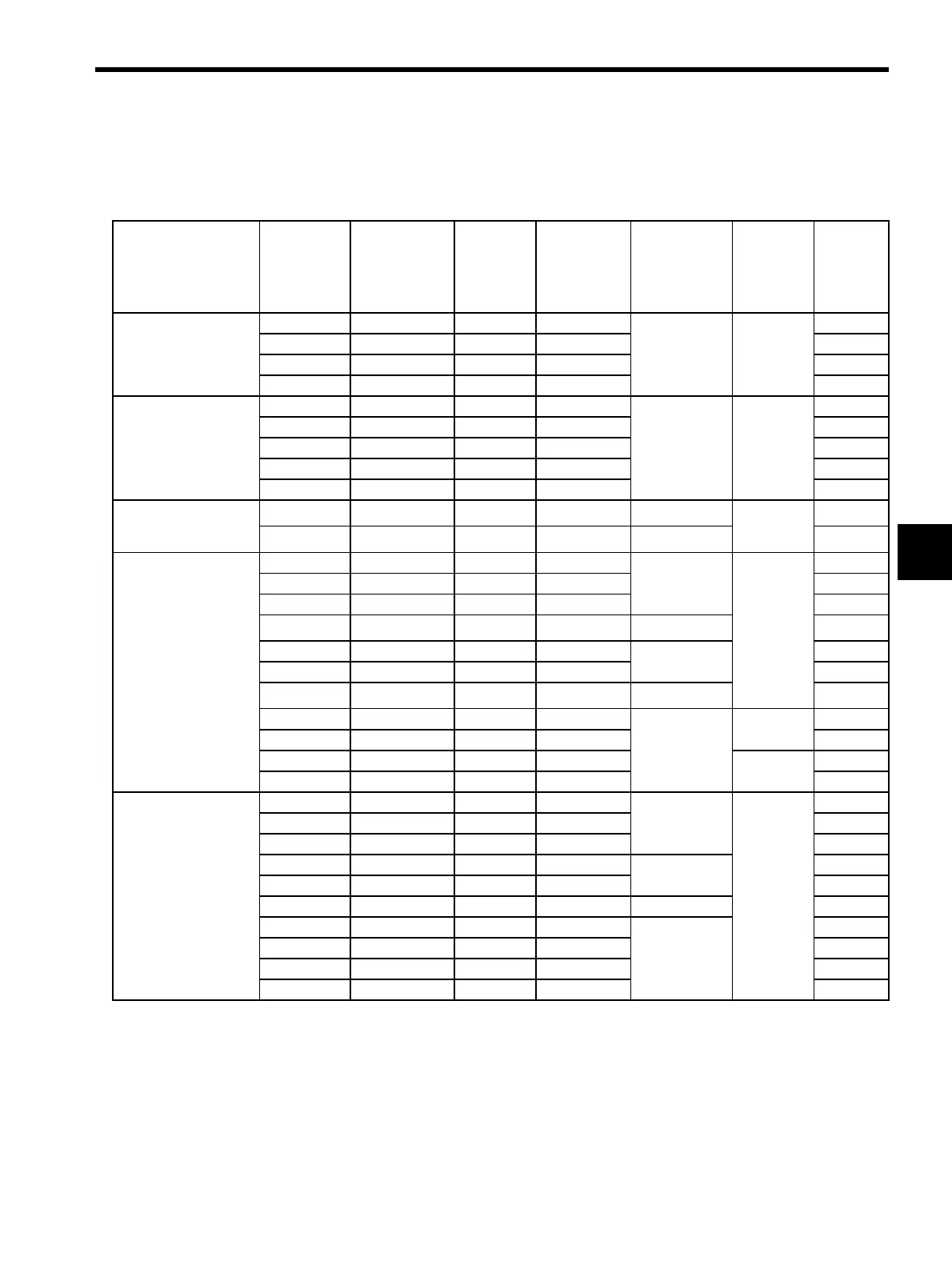
The following table shows SERVOPACK’s power supply capacities and power losses at the rated output.
* 1. SERVOPACKs with a capacity of 30 to 400W do not have built-in regenerative resistors. If the
regenerative energy exceeds the specified value, connect an external regenerative resistor. Refer to
11.1.3 Calculating the Required Capacity of Regenerative Resistors.
* 2. Regenerative resistor power losses are allowable losses. Take the following action if this value is
exceeded.
• Remove the lead from the internal regenerative resistor in the SERVOPACK.
• Install an external regenerative resistor (optional).
Table 4.1 SERVOPACK Power Losses at Rated Output
Main Circuit Power
Supply
Maximum
Applicable
Servomotor
Capacity
kW
SERVOPACK
Model
SGDH-
Output
Current
(Effective
Value)
A
Main Circuit
Power Loss
W
Regenerative
Resistor
Power Loss
W
Control
Circuit
Power
Loss
W
Total
Power
Loss
W
Single-phase 100 V
0.03 A3BE 0.66 3.5
−
∗1
13 16.5
0.05 A5BE 0.95 5.2 18.2
0.10 01BE 2.4 12 25
0.20 02BE 3.0 16.4 29.4
Single-phase 200 V
0.03 A3AE 0.44 3.1
−
∗1
13 16.1
0.05 A5AE 0.64 4.6 17.6
0.10 01AE 0.91 6.7 19.7
0.20 02AE 2.1 13.3 26.3
0.40 04AE 2.8 20 33
Single-phase 220 V
0.75 08AE-S 4.4 47
12
∗2
15 74
1.50 15AE-S 7.5 60
14
∗2
89
Three-phase 200 V
0.45 05AE 3.8 27
12
∗2
15 54
0.75 08AE 5.7 41 68
1.0 10AE 7.6 55 82
1.5 15AE 11.6 92
14
∗2
121
2.0 20AE 18.5 120
28
∗2
163
3.0 30AE 24.8 155 198
5.0 50AE 32.9 240
56
∗2
311
6.0 60AE 46.9 290
−
∗3
27 317
7.5 75AE 54.7 330 357
11 1AAE 58.6 360 30 390
15 1EAE 78.0 490 520
Three-phase 400 V
0.45 05DE 1.9 19
14
∗2
15 48
1.0 10DE 3.5 35 64
1.5 15DE 5.4 53 82
2.0 20DE 8.4 83
28
∗2
126
3.0 30DE 11.9 118 161
5.0 50DE 16.5 192 36 243
6.0 60DE 20.8 232
−
∗3
247
7.5 75DE 25.4 264 279
11 1ADE 28.1 288 303
15 1EDE 37.2 392 407

 Loading...