12.3 List of Parameters
12-37
12
* When Pn50A.0 is set to 0 for the input signal standard allocation mode, the following modes are compatible:
Pn50A.1 = 7, Pn50A.3 = 8, and Pn50B.0 = 8.
Input signal polarities
Parameter
No.
Name Setting Range Unit
Factory
Setting
Setting
Validation
Reference
Section
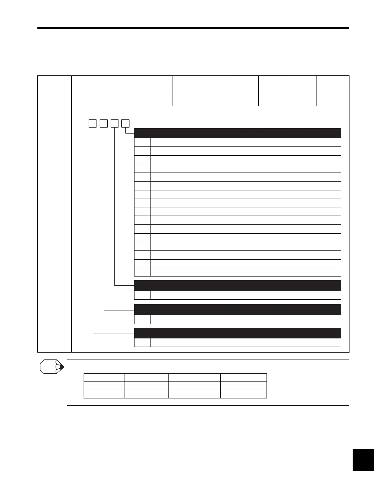
Pn50B Input Signal Selections 2
−−6543 After
restart
−
0
1
2
3
4
5
6
7
8
9
A
B
Reverse run allowed when CN1-40 input signal is ON (L-level).
Reverse run allowed when CN1-41 input signal is ON (L-level).
Reverse run allowed when CN1-42 input signal is ON (L-level).
Reverse run allowed when CN1-43 input signal is ON (L-level).
Reverse run allowed when CN1-44 input signal is ON (L-level).
Reverse run allowed when CN1-45 input signal is ON (L-level).
Reverse run allowed when CN1-46 input signal is ON (L-level).
Reverse run prohibited.
Reverse run allowed.
Reverse run allowed when CN1-40 input signal is OFF (H-level).
Reverse run allowed when CN1-41 input signal is OFF (H-level).
Reverse run allowed when CN1-42 input signal is OFF (H-level).
0 to F
Same as N-OT
0 to F
Same as /S-OT, the setting of 2nd digit of Pn50A
4th
digit
3rd
digit
2nd
digit
1st
digit
n.
Reverse run allowed when CN1-43 input signal is OFF (H-level).
Reverse run allowed when CN1-44 input signal is OFF (H-level).
Reverse run allowed when CN1-45 input signal is OFF (H-level).
Reverse run allowed when CN1-46 input signal is OFF (H-level).
C
D
E
F
/P-CL Signal Mapping (Torque Limit when ON (L-level))
(Refer to "8.9.2 External Torque Limit (Output Torque Limiting by Input Signals).")
0 to F
Same as /S-OT, the setting of 2nd digit of Pn50A
/N-CL Signal Mapping (Torque Limit when ON (L-level))
(Refer to "8.9.2 External Torque Limit (Output Torque Limiting by Input Signals).")
N-OT Signal Mapping (Overtravel when OFF (H-level))
(Refer to "8.3.3 Setting the Overtravel Limit Function.")
/ALM-RST Signal Mapping (Alarm Reset when ON (L-level))
(Refer to "8.11.1 Servo Alarm Output (ALM) and Alarm Code Output (ALO1, ALO2, ALO3).")
Signal Effective Level Voltage level Contact
ON Low (L) level 0 V Close
OFF High (H) level 24 V Open
INFO
Artisan Technology Group - Quality Instrumentation ... Guaranteed | (888) 88-SOURCE | www.artisantg.com
 Loading...


