CELL-DYN 3000 System Operator’s Manual 12-7
9140240E — May 1995
Chapter 12 Sample Loader
Operating Principles
Functional Description
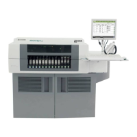
The Sample Loader is designed to fit directly in front of the Analyzer. A
metal platform attached to the front of the Analyzer pedestal provides an
extension to support the Sample Loader. (See Figure 12.1.)
Five tubes (one aspiration, two rinse and two waste) are connected from
the Sample Loader tower to the Analyzer flow panel. A communication
cable is connected from the Sample Loader’s right side panel to the
Analyzer’s left side panel. The Sample Loader operation keyboard is
located on the right side of the main module. (See Figure 12.4.)
Three stations located on the Sample Loader tower unit are used to vent,
mix, and aspirate each sample tube. (See Figure 12.6.) A tube detection
sensor checks for the presence of a tube at Station 1. If a tube is detected,
the vent needle punctures the stopper to vent the tube to atmospheric
pressure. At Station 2, the mixing head extends to mix the sample and the
bar code reader simultaneously reads any bar code label present. Mixing
is done by rotating the tube in both directions. If the mixing head
contacts a tube that was not sensed at Station 1, a fault occurs. At
Station 3, the aspiration needle extends to puncture the tube stopper and
aspirate the mixed sample.