12-8 CELL-DYN 3000 System Operator’s Manual
9140240E — May 1995
Sample Loader Chapter 12
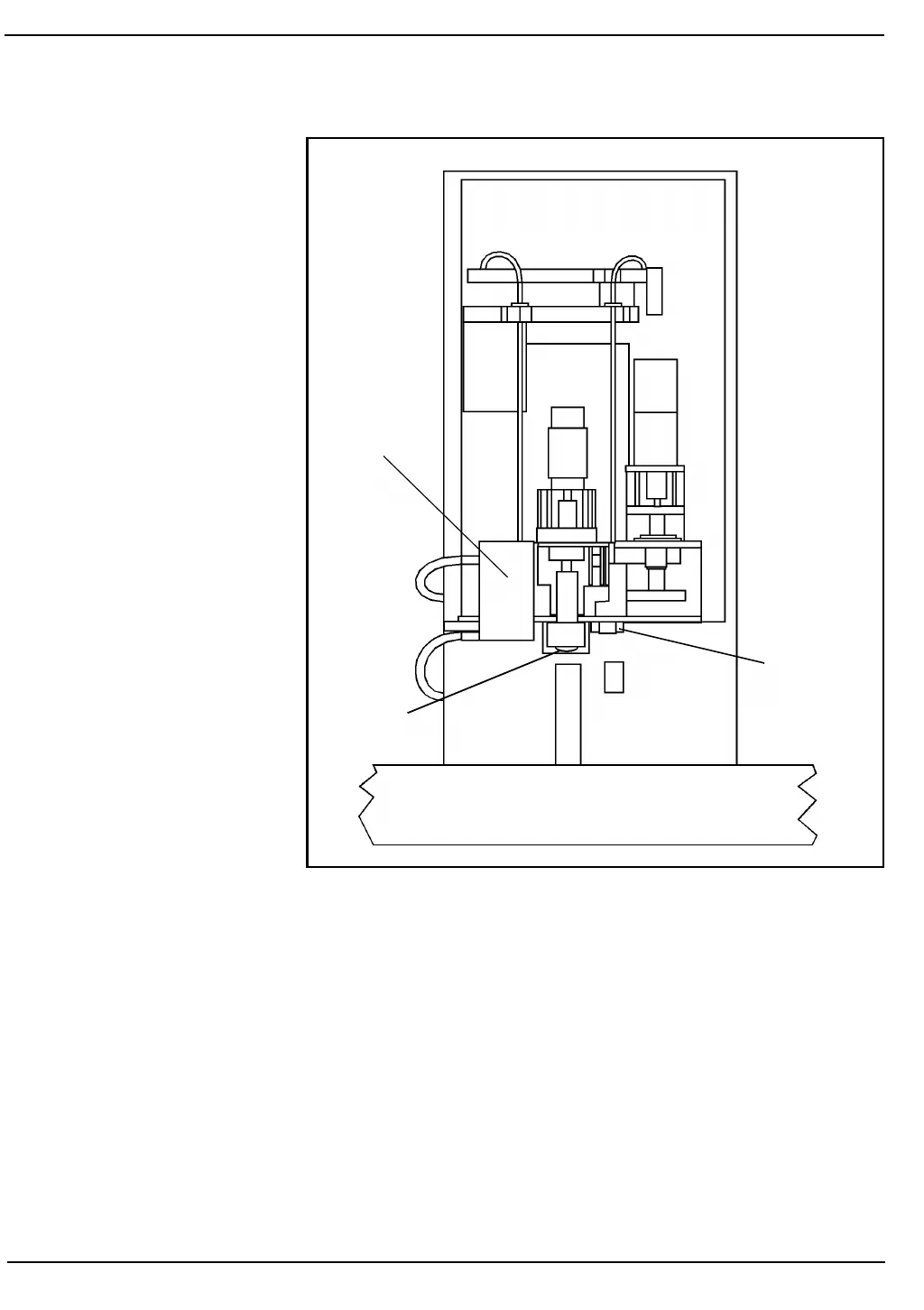
Figure 12.6: Tower Stations
When the tube is at Station 1 or Station 3, a plunger (vial positioning
mechanism) positions the tube vertically in the rack and holds it while
the tube is vented or the sample is aspirated. This enables the tube
stopper to be pierced in the center and the rack to accommodate tubes
with varying numbers of labels.
Ten tube racks must be in place for Sample Loader operation. The end
rack is marked with black labels on top and a black label on the left end
of the rack. (See Figure 12.7.) This rack is used to indicate the last rack
of a specific run. The Sample Loader automatically stops when the end
rack reaches the left rear corner of the tray.
Station 3
Station 2
Station 1
Venting
Aspirating
Mixing