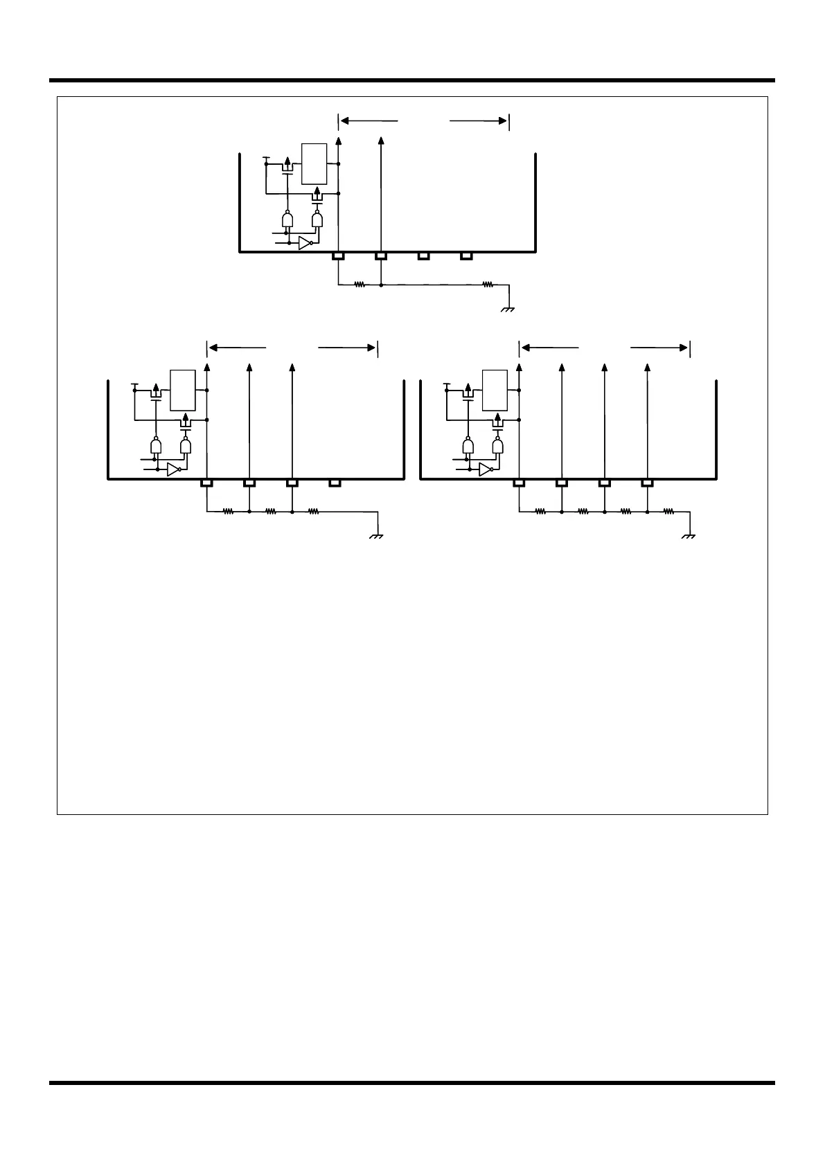
NOTE)
1. When the external resistor bias is selected, the internal resistors for bias are disconnected.
2. When the external resistor bias is selected, the dividing resistors should be connected like
the above figure and the needed bias pins should be selected as the LCD bias function
pins (VLC0, VLC1, VLC2 and VLC3) by P7FSRL register.
- When it is 1/2 bias, the P73/VLC0 and P72/VLC1 pins should be selected as VLC0 and
VLC1
functions. The other pins can be used for normal I/O.
- When it is 1/3 bias, the P73/VLC0, P72/VLC1 and P71/VLC2 pins should be selected as
VLC0,
VLC1 and VLC2 functions. The P70/VLC3 pin can be used for normal I/O.
- When it is 1/4 bias, the P73/VLC0, P72/VLC1, P71/VLC2 and P70/VLC3 pins should be
selected
as VLC0, VLC1, VLC2 and VLC3 functions.