Repairing the Fluorescence Detector 5
1100 Series FD Reference Manual 151
11
Place the pad with the holder on the stand-offs. The
”TOP” sign should be directed towards the trigger pack.
Refit the screws.
Note:
During the next step no horizontal movement should
be made to the pad.
12
While pressing the top pad down onto the stand-offs,
tighten the screws. Turn the trigger pack such as its
marker stays in line with the “TOP” sign of the brass
holder.
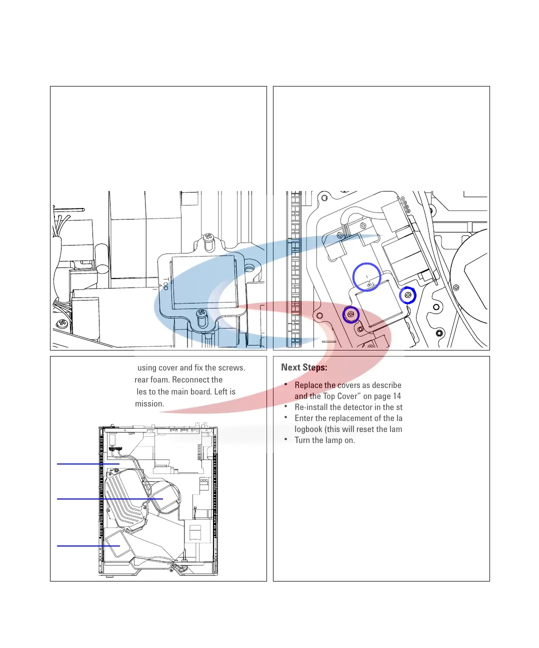
13 Replace the lamp housing cover and fix the screws.
Carefully insert the rear foam. Reconnect the
monochromator cables to the main board. Left is
excitation, right is emission.
Next Steps:
• Replace the covers as described in “Replacing the Foam
and the Top Cover” on page 149.
• Re-install the detector in the stack.
• Enter the replacement of the lamp in the maintenance
logbook (this will reset the lamp counter).
• Turn the lamp on.
• Perform a wavelength verification to check the correct
positioning of the replaced assemblies, as described in
chapter “Wavelength Verification and Calibration" on
page 101.
A
B
A
B
A
Rear
foam
EM
EX
 Loading...


