22 1100 Series FD Reference Manual
1 Installing the Fluorescence Detector
Installing the Detector
1 Install the LAN interface board in the detector (if required), see “Replacing
the Interface Board" on page 199.
2 Place the detector in the stack or on the bench in a horizontal position.
3 Ensure the line power switch at the front of the detector is OFF.
4 Connect the power cable to the power connector at the rear of the detector.
5 Connect the CAN cable to other Agilent 1100 Series modules.
6 If a Agilent ChemStation is the controller, connect either
• the GPIB cable to the detector or
• the LAN connection to the LAN interface board in the detector.
7 Connect the analog cable(s) (optional).
Preparations Locate bench space
Provide power connections
Unpack the detector
Parts required Detector
Power cord, for other cables see below and “Cable Overview" on page 218,
ChemStation and/or Control Module G1323A/B.
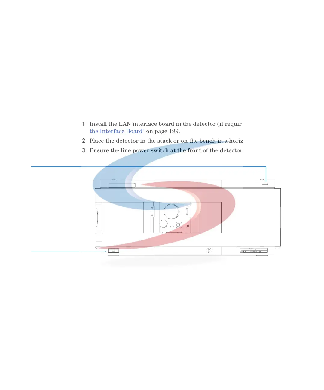
Figure 5 Front View of Detector
Line power switch
with green light
Status indicator
green/yellow/red
 Loading...


