Installing the Fluorescence Detector 1
1100 Series FD Reference Manual 23
8 Connect the APG remote cable (optional) for non-Agilent 1100 Series
instruments.
9 Turn on power by pushing the button at the lower left hand side of the
detector. The status LED should be green.
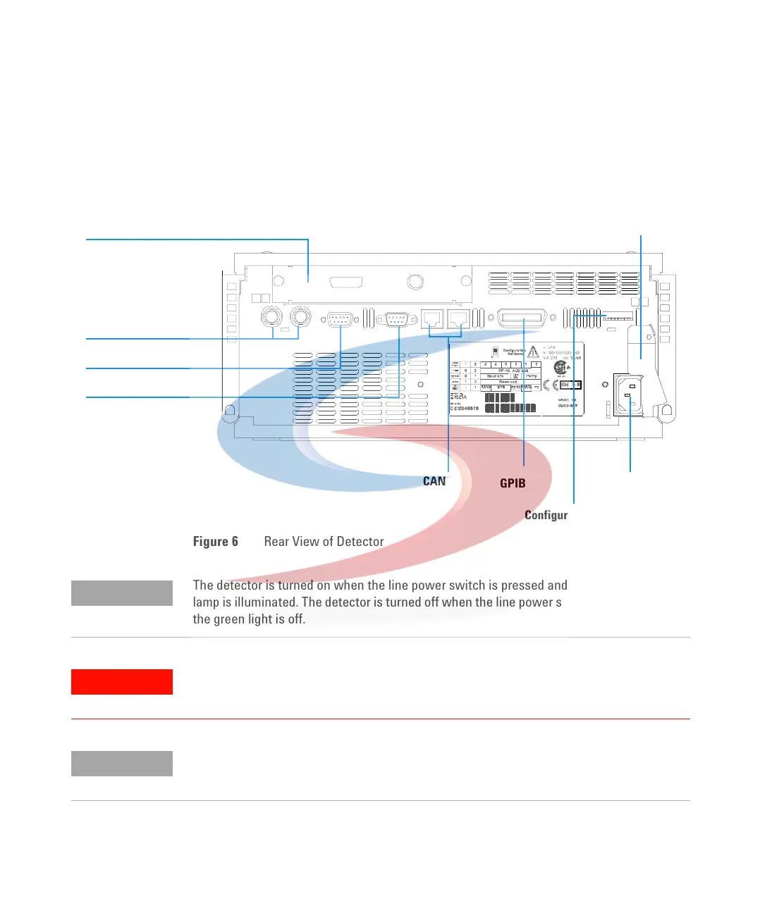
Figure 6 Rear View of Detector
Analog signal
APG remote
RS-232C
CAN
GPIB Power
Configuration switch
Interface board
LAN or BCD/EXT
Security lever
NOTE
The detector is turned on when the line power switch is pressed and the green indicator
lamp is illuminated. The detector is turned off when the line power switch is protruding and
the green light is off.
WARNING
To disconnect the detector from line, unplug the power cord. The power supply still
uses some power, even if the power switch at the front panel is turned off.
NOTE
The detector was shipped with default configuration settings. To change these settings see
“Setting the 8-bit Configuration Switch" on page 290.
 Loading...


