Theory of Operation 8
1100 Series FD Reference Manual 271
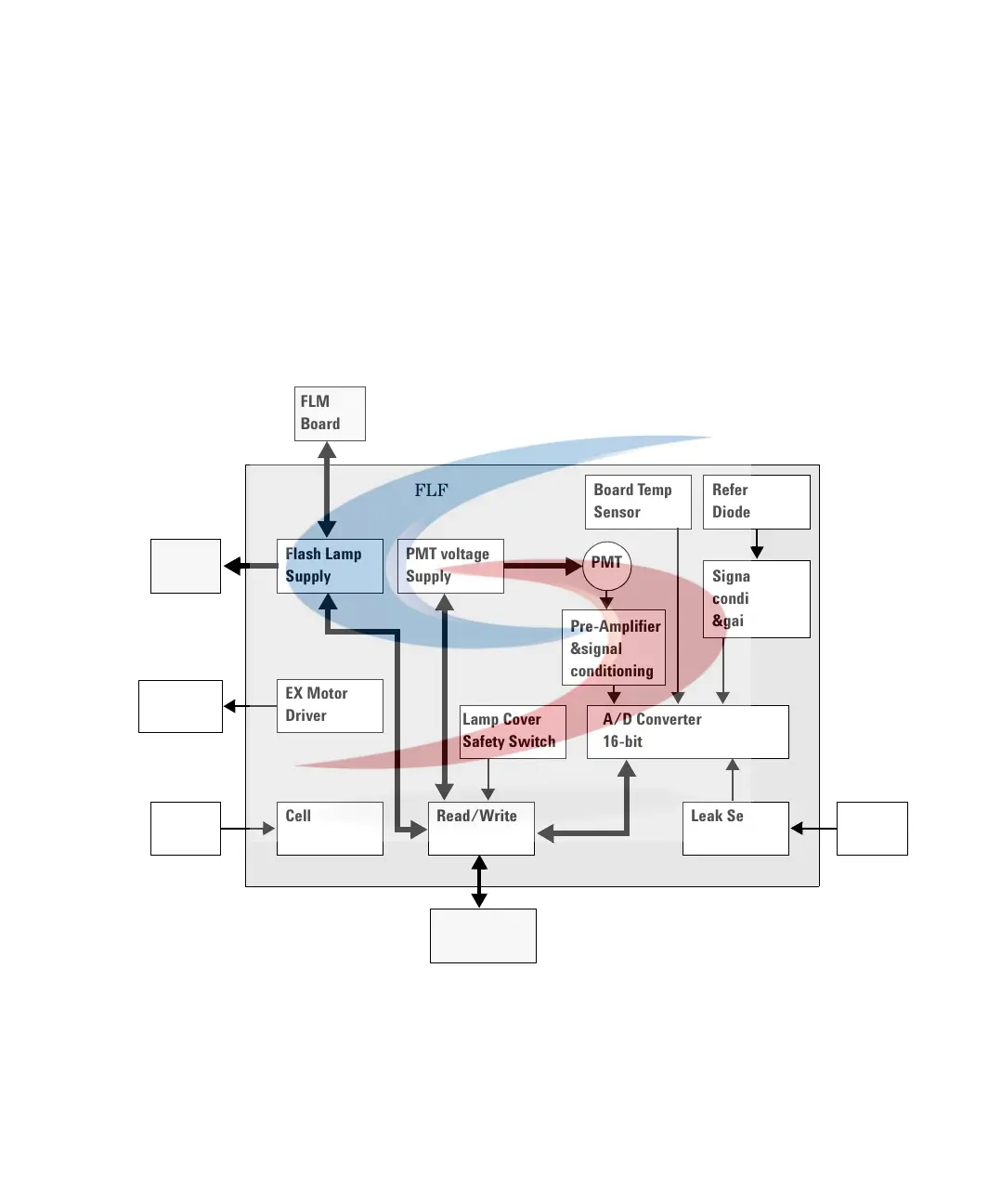
Photomultiplier Tube Voltage Supply
The photomultiplier tube needs an adjustable working voltage between -240 V
and -820 V for correct operation. The PMT gains are realized by variable
operating voltage of the device. A regulated pulse width modulator is used to
generate the high voltage by switching the 24 V rail to a transformer. The
feedback loop has a D/A-converter-controlled base voltage to set the desired
output voltage. The PMT output delivers a current signal which is proportional
to the detected light and to the actual working voltage.
Figure 92 Block diagram FLF
Flash Lamp
Supply
PMT voltage
Supply
EX Motor
Driver
Cell
Detection
Read/Write
Port
Leak Sensor
circuit
A/D Converter
16-bit
Lamp Cover
Safety Switch
Reference
Diode
Signal
conditioning
&gain
Pre-Amplifier
&signal
conditioning
Board Temp
Sensor
PMT
Leak
Sensor
Flow
Cell
EX Mono-
chromator
FLL
Board
FLM
Board
FLF
FLM
Board
 Loading...


