11 Configuration
170 Operation Manual
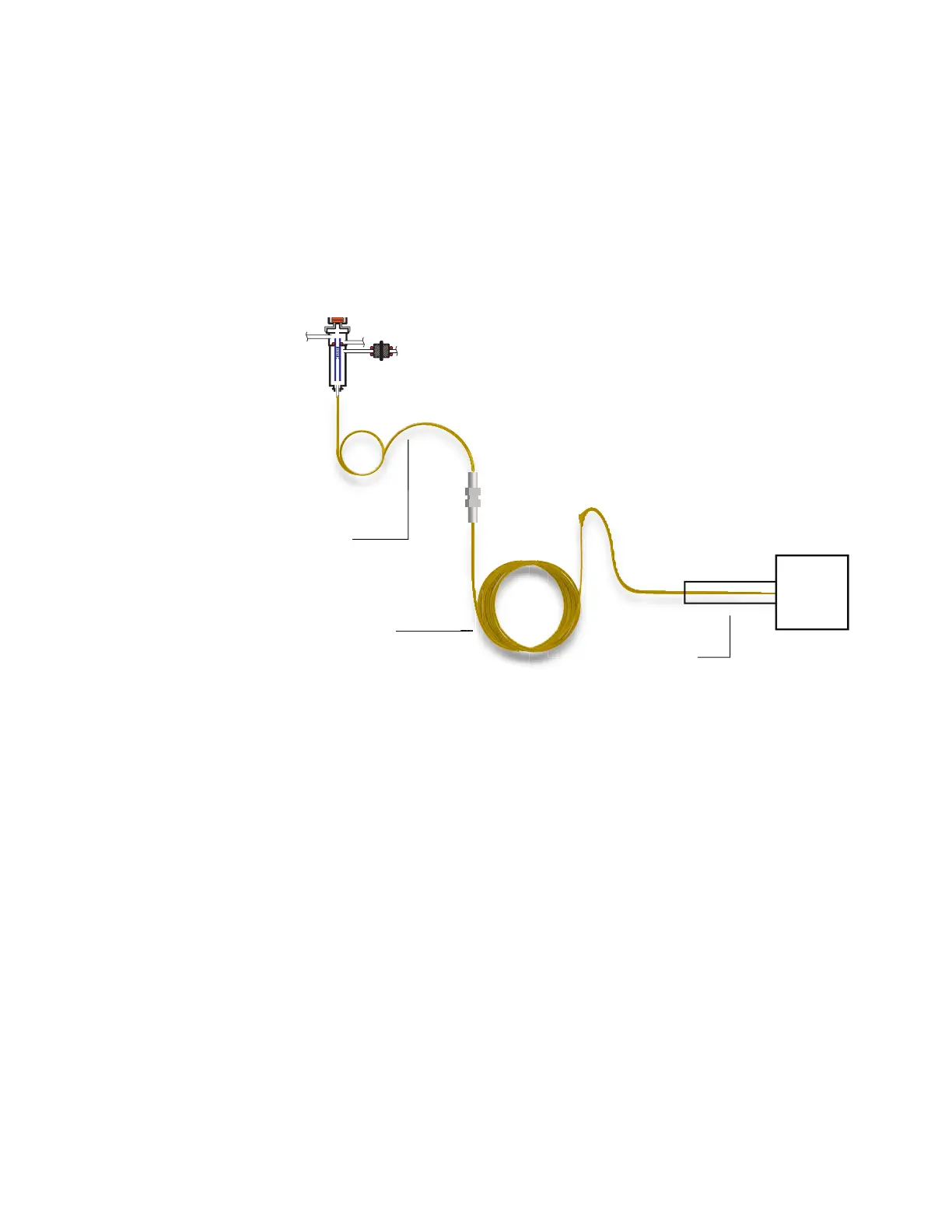
diameters, and film thicknesses can be specified separately. Also, the zones that determine
the temperatures of each of the four segments are specified separately. The three additional
segments are often uncoated (zero film thickness) and, serving as connectors, are of shorter
length than the main segment. It is necessary to specify these additional segments so that the
flow-pressure relationship for the composite column can be determined.
Composite columns differ from multiple columns because for composite columns, 100% of
the column flow continues through a single column or through multiple column segments
without additional makeup gas.
To configure a composite column:
1 Select Settings > Configuration > Columns.
2 Under Column Type, select Composite from the dropdown menu.
3 Input the Length, Diameter, and Film Thickness into the appropriate fields.
4 Under Inlet connection, select the desired inlet from the dropdown menu. Selections
include the installed GC inlets, and installed Aux and PCM channels.
5 Under Outlet connection, select the desired outlet from the dropdown menu.
6 Under Thermal zone, select the desired thermal zone from the dropdown menu.
7 Select the down arrow on the right side of the window to view additional settings.
8 In the second screen, set the Length, Diameter, and Film Thickness for each segment.
9 In the Heated By column, select the heating source for each column segment from the
dropdowns.
10 In the third screen, set the Min Temp, Max Temp, and Max Program Temp for your column.
11 In the fourth screen, you can set the column’s
• Manufacturer
Analytical column
MSD
Transfer Line
In segment
Out segment
Transfer Line

 Loading...


