183
8331B–AVR–03/12
Atmel AVR XMEGA AU
• Bit 3 – Reserved
This bit is unused and reserved for future use. For compatibility with future devices, always write
this bit to zero when this register is written.
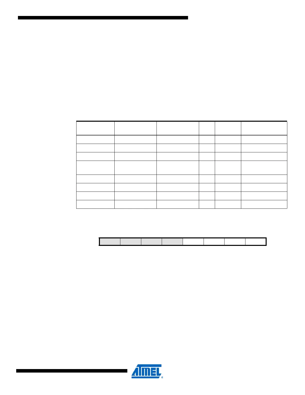
• Bit 2:0 – WGMODE[2:0]: Waveform Generation Mode
These bits select the waveform generation mode, and control the counting sequence of the
counter, TOP value, UPDATE condition, interrupt/event condition, and type of waveform that is
generated according to Table 14-4 on page 183.
No waveform generation is performed in the normal mode of operation. For all other modes, the
result from the waveform generator will only be directed to the port pins if the corresponding
CCxEN bit has been set to enable this. The port pin direction must be set as output.
14.12.3 CTRLC – Control register C
• Bit 7:4 – Reserved
These bits are unused and reserved for future use. For compatibility with future devices, always
write these bits to zero when this register is written.
• Bit 3:0 – CMPx: Compare Output Value x
These bits allow direct access to the waveform generator's output compare value when the
timer/counter is set in the OFF state. This is used to set or clear the WG output value when the
timer/counter is not running.
Table 14-4. Timer waveform generation mode.
WGMODE[2:0]
Group
Configuration
Mode of
Operation Top Update OVFIF/Event
000 NORMAL Normal PER TOP TOP
001 FRQ Frequency CCA TOP TOP
010 Reserved - - -
011 SINGLESLOPE
Single-slope
PWM
PER BOTTOM BOTTOM
100 Reserved - - -
101 DSTOP Dual-slope PWM PER BOTTOM TOP
110 DSBOTH Dual-slope PWM PER BOTTOM TOP and BOTTOM
111 DSBOTTOM Dual-slope PWM PER BOTTOM BOTTOM
Bit 76543210
+0x02 – – – – CMPD CMPC CMPB CMPA CTRLC
Read/Write R R R R R/W R/W R/W R/W
Initial Value00000000

 Loading...


