184
8331B–AVR–03/12
Atmel AVR XMEGA AU
14.12.4 CTRLD – Control register D
• Bit 7:5 – EVACT[2:0]: Event Action
These bits define the event action the timer will perform on an event according to Table 14-5 on
page 184.
The EVSEL setting will decide which event source or sources have control in this case.
Selecting any of the capture event actions changes the behaviour of the CCx registers and
related status and control bits to be used for capture. The error status flag (ERRIF) will indicate a
buffer overflow in this configuration. See ”Event Action Controlled Operation” on page 173 for
futher details.
• Bit 4 – EVDLY: Timer Delay Event
When this bit is set, the selected event source is delayed by one peripheral clock cycle. This is
intended for 32-bit input capture operation. Adding the event delay is necessary to compensate
for the carry propagation delay when cascading two counters via the event system.
• Bit 3:0 – EVSEL[3:0]:Timer Event Source Select
These bits select the event channel source for the timer/counter. For the selected event channel
to have any effect, the event action bits (EVACT) must be set according to Table 14-6. When the
event action is set to a capture operation, the selected event channel n will be the event channel
source for CC channel A, and event channel (n+1)%8, (n+2)%8, and (n+3)%8 will be the event
channel source for CC channel B, C, and D.
Bit 76543210
+0x03 EVACT[2:0] EVDLY EVSEL[3:0] CTRLD
Read/Write R/W R/W R/W R/W R/W R/W R/W R/W
Initial Value 0 0 0 0 0 0 0 0
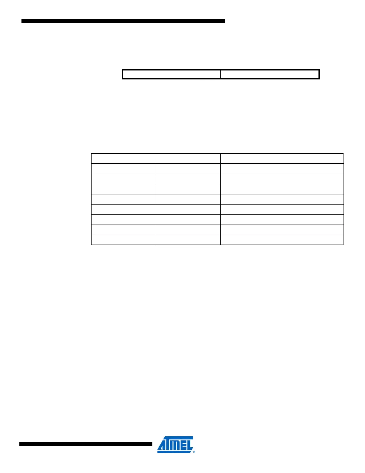
Table 14-5. Timer event action selection.
EVACT[2:0] Group Configuration Event Action
000 OFF None
001 CAPT Input capture
010 UPDOWN Externally controlled up/ down count
011 QDEC Quadrature decode
100 RESTART Restart waveform period
101 FRQ Frequency capture
110 PW Pulse width capture
111 Reserved

 Loading...


