185
8331B–AVR–03/12
Atmel AVR XMEGA AU
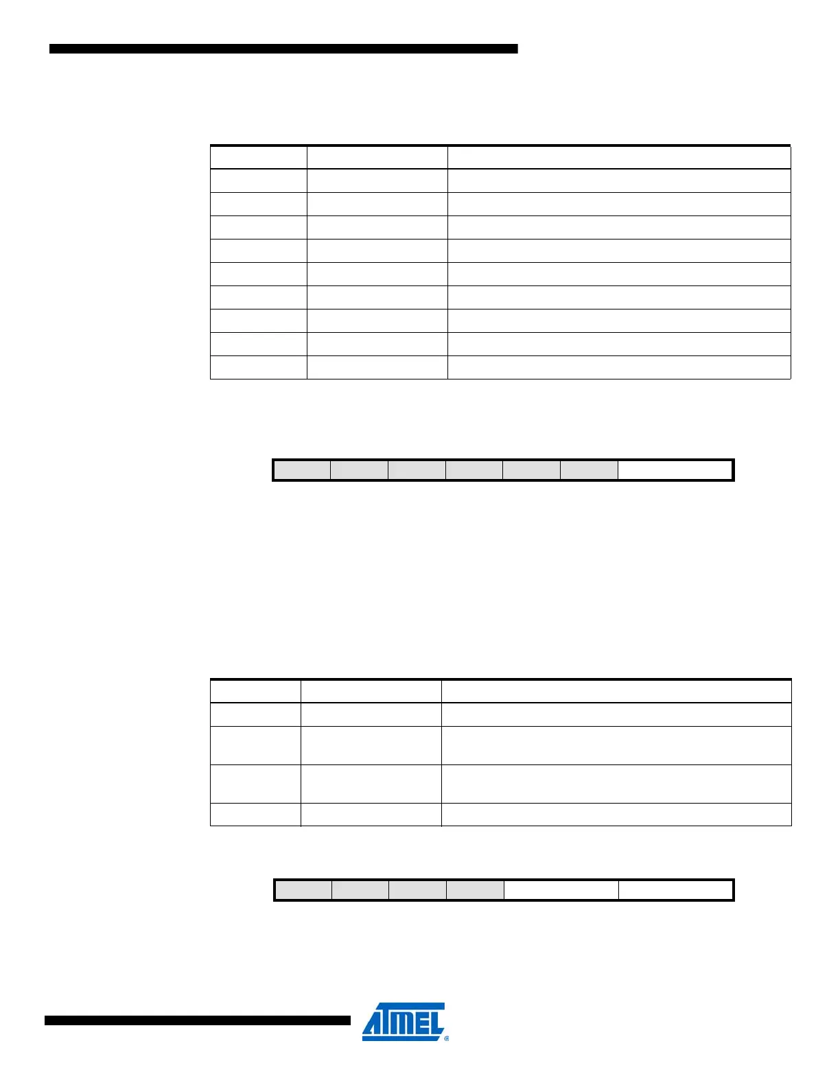
14.12.5 CTRLE – Control register E
• Bit 7:2 – Reserved
These bits are unused and reserved for future use. For compatibility with future devices, always
write these bits to zero when this register is written.
• Bit 1:0 – BYTEM[1:0]: Byte Mode
These bits select the timer/counter operation mode according to Table 14-7 on page 185.
14.12.6 INTCTRLA – Interrupt Enable register A
Table 14-6. Timer event source selection.
EVSEL[3:0] Group Configuration Event Source
0000 OFF None
0001 Reserved
0010 Reserved
0011 Reserved
0100 Reserved
0101 Reserved
0110 Reserved
0111 Reserved
1nnn CHn Event channel n, n={0,...,7}
Bit 76543210
+0x04 – – – – – – BYTEM[1:0] CTRLE
Read/WriteRRRRRRRR/W
Initial Value00000000
Table 14-7. Clock select.
BYTEM[1:0] Group Configuration Description
00 NORMAL Timer/counter is set to normal mode (timer/counter type 0)
01 BYTEMODE
Upper byte of the counter (CNTH) will be set to zero after
each counter clock cycle
10 SPLITMODE
Timer/counter 0 is split into two 8-bit timer/counters
(timer/counter type 2)
11 Reserved
Bit 76543210
+0x06 – – – – ERRINTLVL[1:0] OVFINTLVL[1:0] INTCTRLA
Read/WriteRRRRR/WR/WR/WR/W
Initial Value00000000

 Loading...


