186
8331B–AVR–03/12
Atmel AVR XMEGA AU
• Bit 7:4 – Reserved
These bits are unused and reserved for future use. For compatibility with future devices, always
write these bits to zero when this register is written.
• Bit 3:2 – ERRINTLVL[1:0]:Timer Error Interrupt Level
These bits enable the timer error interrupt and select the interrupt level as described in ”Inter-
rupts and Programmable Multilevel Interrupt Controller” on page 134.
• Bit 1:0 – OVFINTLVL[1:0]:Timer Overflow/Underflow Interrupt Level
These bits enable the timer overflow/underflow interrupt and select the interrupt level as
described in ”Interrupts and Programmable Multilevel Interrupt Controller” on page 134.
14.12.7 INTCTRLB – Interrupt Enable register B
• Bit 7:0 – CCxINTLVL[7:0] - Compare or Capture x Interrupt Level:
These bits enable the timer compare or capture interrupt for channel x and select the interrupt
level as described in ”Interrupts and Programmable Multilevel Interrupt Controller” on page 134.
14.12.8 CTRLFCLR/CTRLFSET – Control register F Clear/Set
This register is mapped into two I/O memory locations, one for clearing (CTRLxCLR) and one for
setting the register bits (CTRLxSET) when written. Both memory locations will give the same
result when read.
The individual status bit can be set by writing a one to its bit location in CTRLxSET, and cleared
by writing a one to its bit location in CTRLxCLR. This allows each bit to be set or cleared without
use of a read-modify-write operation on a single register.
• Bit 7:4 – Reserved
These bits are unused and reserved for future use. For compatibility with future devices, always
write these bits to zero when this register is written.
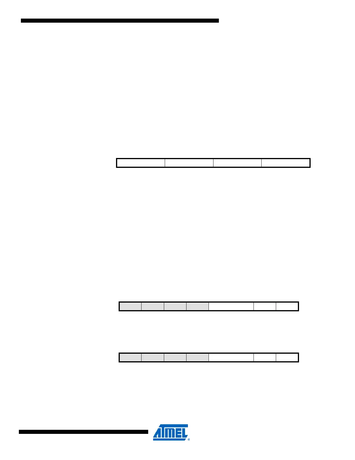
Bit 76543210
+0x07 CCDINTLVL[1:0] CCCINTLVL[1:0] CCBINTLVL[1:0] CCAINTLVL[1:0] INTCTRLB
Read/Write R/W R/W R/W R/W R/W R/W R/W R/W
Initial Value00000000
Bit 76543210
+0x08 – – – – CMD[1:0] LUPD DIR CTRLFCLR
Read/WriteRRRRRRR/WR/W
Initial Value00000000
Bit 76543210
+0x09
– – – – CMD[1:0] LUPD DIR CTRLFSET
Read/Write R R R R R/W R/W R/W R/W
Initial Value00000000
 Loading...


