371
8331B–AVR–03/12
Atmel AVR XMEGA AU
• Bit 6:5 – CURRLIMIT[1:0]: Current Limitation
These bits can be used to limit the current consumption of the ADC by reducing the maximum
ADC sample rate. The available settings are shown in Table 28-3 on page 371. The indicated
current limitations are nominal values. Refer to the device datasheet for actual current limitation
for each setting.
• Bit 4 – CONVMODE: Conversion Mode
This bit controls whether the ADC will work in signed or unsigned mode. By default, this bit is
cleared and the ADC is configured for unsigned mode. When this bit is set, the ADC is config-
ured for signed mode.
• Bit 3 – FREERUN: Free Running Mode
When the bit is set to one, the ADC is in free running mode and the ADC channels defined in the
EVCTRL register are swept repeatedly.
• Bit 2:1 – RESOLUTION[1:0]: Conversion Result Resolution
These bits define whether the ADC completes the conversion at 12- or 8-bit result resolution.
They also define whether the 12-bit result is left or right adjusted within the 16-bit result regis-
ters. See Table 28-4 on page 371 for possible settings.
• Bit 0 - Reserved
This bit is unused and reserved for future use. For compatibility with future devices, always write
this bit to zero when this register is written.
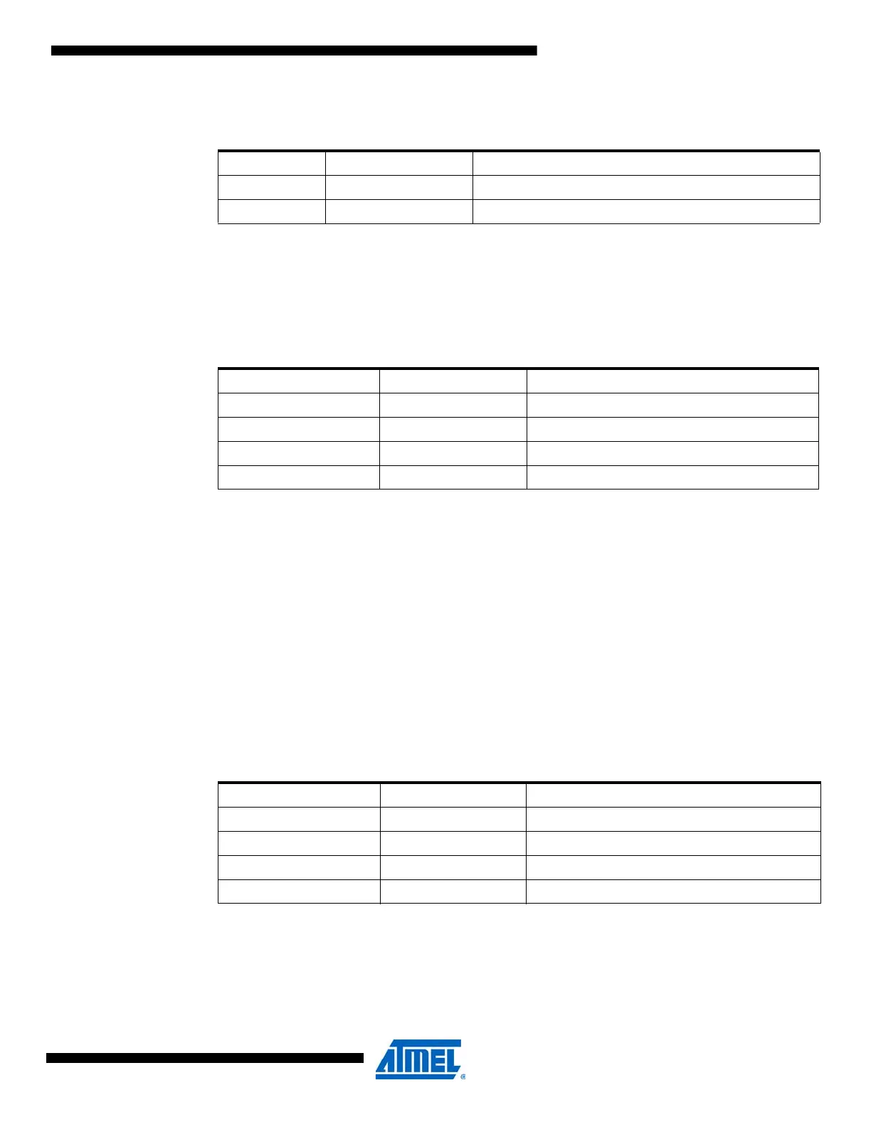
Table 28-2. Gain stage impedance mode.
IMPMODE Group Configuration Description
0 HIGHIMP For high-impedance sources; charge will remain on input
1 LOWIMP For low impedance sources
Table 28-3. ADC current limitations.
CURRLIMIT[1:0] Group Configuration Description
00 NO No limit
01 LOW Low current limit, max. sampling rate 1.5MSPS
10 MED Medium current limit, max. sampling rate 1MSPS
11 HIGH High current limit, max. sampling rate 0.5MSPS
Table 28-4. ADC conversion result resolution.
RESOLUTION[1:0] Group Configuration Description
00 12BIT 12-bit result, right adjusted
01 Reserved
10 8BIT 8-bit result, right adjusted
11 LEFT12BIT 12-bit result, left adjusted

 Loading...


