417
8331B–AVR–03/12
Atmel AVR XMEGA AU
32.3.1 Enabling
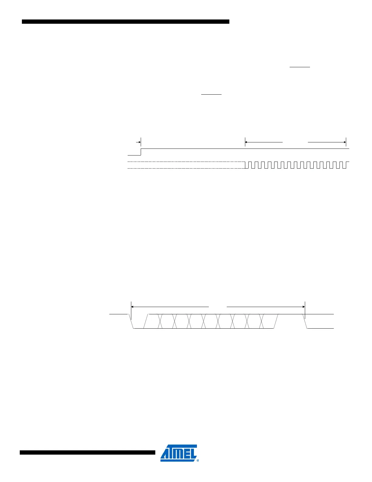
The PDI physical layer must be enabled before use. This is done by first forcing the PDI_DATA
line high for a period longer than the equivalent external reset minimum pulse width (refer to
device datasheet for external reset pulse width data). This will disable the RESET
functionality of
the Reset pin, if not already disabled by the fuse settings.
Next, continue to keep the PDI_DATA line high for 16 PDI_CLK cycles. The first PDI_CLK cycle
must start no later than 100µs after the RESET
functionality of the Reset pin is disabled. If this
does not occur in time, the enabling procedure must start over again. The enable sequence is
shown in Figure 32-3 on page 417.
Figure 32-3. PDI physical layer enable sequence.
The Reset pin is sampled when the PDI interface is enabled. The reset register is then set
according to the state of the Reset pin, preventing the device from running code after the reset
functionality of this pin is disabled.
32.3.2 Disabling
If the clock frequency on PDI_CLK is lower than approximately 10kHz, this is regarded as inac-
tivity on the clock line. This will automatically disable the PDI. If not disabled by a fuse, the reset
function of the Reset (PDI_CLK) pin is enabled again. This also means that the minimum pro-
gramming frequency is approximately 10kHz.
32.3.3 Frame Format and Characters
The PDI physical layer uses a frame format defined as one character of eight data bits, with a
start bit, a parity bit, and two stop bits.
Figure 32-4. PDI serial frame format.
Disable RESET function on Reset (PDI_CLK) pin
Activate PDI
PDI_DATA
PDI_CLK
St Start bit, always low
(0-7) Data bits (0 to 7)
P Parity bit, even parity used
Sp1 Stop bit 1, always high
Sp2 Stop bit 2, always high
St
012
3
4567P
Sp1
FRAME
Sp2(IDLE) (St/IDLE)

 Loading...


