4 - 58
Park the bike on a level surface.
IMPORTANT NOTICE
Prop the bike on suitable supports so that it cannot fall.
NOTE:________________________________
Direct a jet of compressed air between the left of the handle-
bar and the relevant grip, so that it can be slid off the handle-
bar gradually.
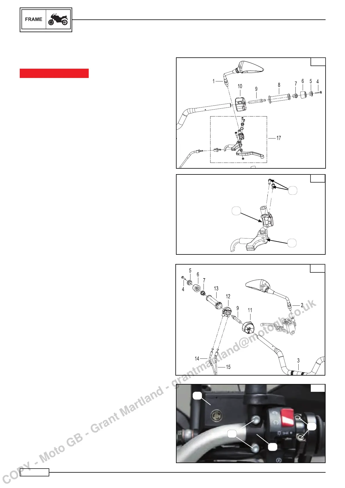
Remove:
• right rear-view mirror (2*) and left rear-view mirror (1*)
• screws (4*) Fig. A
• cap (5*) Fig. A
• handgrip terminal (6*) Fig. A
• threaded insert (7*) Fig. A
• threaded insert (9*) Fig. A
• left handgrip (8*) Fig. A
• screws (B) left commutator switch (C) Fig. B
• left commutator switch (10*) Fig. A
• screws (1) clutch control Fig. B
• U-clamp (2) clutch control (3) Fig. B
• clutch control (17*)
NOTE:________________________________
Disconnect the connector of the LEFT STOP light switch
Remove:
• right commutator switch screws
• Right commutator switch (11*)
• screws (1) Fig. D accelerator control (12*)
• accelerator control (12*)
• Accelerator handgrip (13*)
• Fuel open cable (14*)
• Fuel close cable (15*)
• the screws (2) Fig. D brake pump
• U-clamp (3) brake pump (4) Fig. D.
Remove:
B
2
1
3
HANDLEBAR
HANDLEBAR REMOVAL
A
C
D
1
2
3
4
COPY - Moto GB - Grant Martland - grantmartland@motogb.co.uk
 Loading...