5 - 14
INTAKE CAMSHAFT ASSEMBLY
HEAD DISTRIBUTION
B
X
C
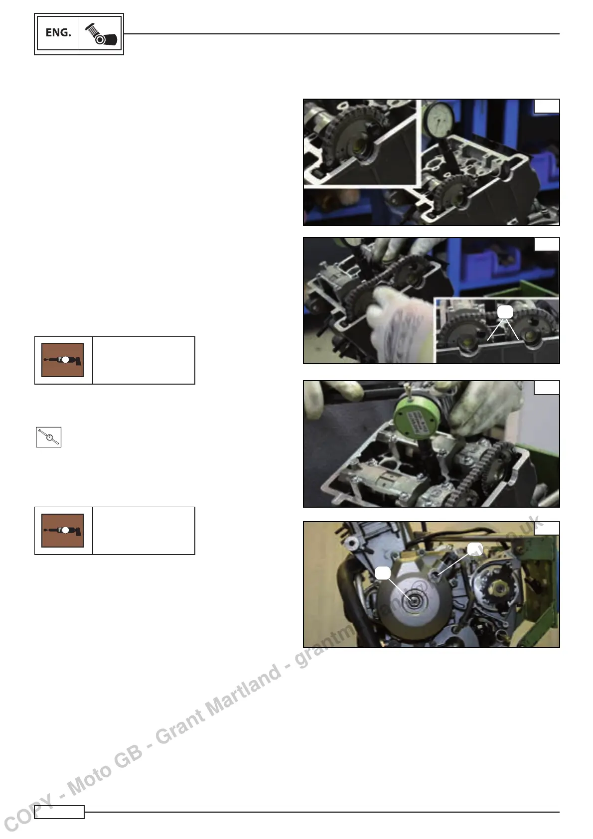
Install the relevant tool (*) into the spark plug seat to check the
top dead centre Fig. A.
(*) Tool: Engine phasing tool
Code:R180197022000
Once the TDC has been identifi ed, proceed to assemble the
camshaft, exhaust side.
NOTE:_________________________________
During installation, it is important for the lobes of cylinder
1 shaft are positioned outwards, and the two reference
notches”X” of the two timing gears are aligned as in Fig. B.
NOTE:_________________________________
When assembling the holders, it is necessary to lubricate
them with special grease to prevent the shafts from rotating
dry during initial starting.
G
Sintofl on Grease
When assembling the holders, proceed in the opposite direction
to removal, tightening the screws to the following torque:
T
.
R
.
Torque 10-13 N*m
NOTE:_________________________________
Lubricate the screws with copper grease.
G
Copper grease
Turn the camshaft clockwise, using the fastening nut to the
fl ywheel, moving the TDC so it lines up with the reference mar-
kings “X” on the head surface Fig. B and the reference mark on
the magnet fl ywheel (2) Fig. D.
D
1
2
A
COPY - Moto GB - Grant Martland - grantmartland@motogb.co.uk
 Loading...