5 - 48
Install:
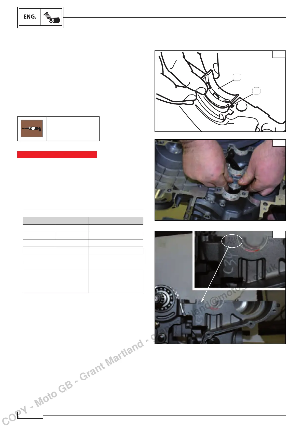
• clean the main bearing shells (6)
• connecting rod main bearing shells:
• install the connecting rod main bearing shells in the relevant
seats in the top and bottom base.
NOTE:_________________________________
Align the projections of the main bearing shells with the
slots in the top base Fig. A.
Use copper grease for assembly.
G
Sintofl on Grease
IMPORTANT NOTICE
Do not get the main bearing shells mixed up.
To achieve the correct clearance between the connecting
rod support and the bearing shells and to prevent engine
damage, the bearing shells must be installed in their origi-
nal positions.
• The crankshaft bearing shells are in different sizes, marked
with different letters and colours, as shown in the table.
MAIN BEARING SHELLS
STD COLOUR THICKNESS
A Green 1.5(0/0 + 0.003) mm
B Blue 1.5(0/0 + 0.006) mm
C Yellow 1.5(0/0 + 0.009) mm
Ø std seat A green Ø 41(0.007+0.14)
Ø std seat B blue Ø 41(0+0.007)
Ø std seat C yellow Ø 41(0.014+0.021)
Ø std seat only A Ø 41(0/+0.007)
B Ø 41(0.007+0.014)
C Ø 41(0.014+0.021)
• The support bearing layout is shown on the bottom casing,
as illustrated in Fig. C.
NOTE:_________________________________
In case of replacement of the drive shaft, it is necessary to
replace the connecting rod main bearing shells.
CRANKCASE
MAIN BEARING SHELL AND DRIVE SHAFT INSTALLATION
B
A
6
A
C
COPY - Moto GB - Grant Martland - grantmartland@motogb.co.uk
 Loading...