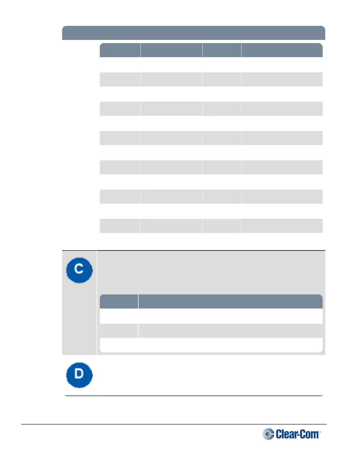
Pin Function Pin Function
Pin 1 Relay 1 NC Pin 14 Relay 1 Pole
Pin 2 Relay 1-NO Pin 15 Relay 2 NC
Pin 3 Relay2-Pole Pin 16 Relay 2-NO
Pin 4 Relay 3 NC Pin 17 Relay 3 Pole
Pin 5 Relay 3-NO Pin 18 Relay 4 NC
Pin 6 Relay4-Pole Pin 19 Relay 4-NO
Pin 7 Pin 20 +5V
Pin 8 GND Pin 21 +5V
Pin 9 GND Pin 22 Opto 1-
Pin 10 Opto 1+ Pin 23 Opto 2-
Pin 11 Opto 2+ Pin 24 Opto 3-
Pin 12 Opto 3+ Pin 25 Opto 4-
Pin 13 Opto 4+
Hot Mic output. This connection is a 1/4-in (0.64 cm) phone jack. It provides an
output signal from the selected headset or panel microphone. The Hot Mic output is
always live. Audio from the mic is routed through the Hot Mic output even if the mic
is inactive (off).
 Loading...