HelixNet | User Guide
Key to analog and digital cabling comparison diagram
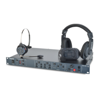
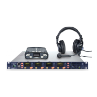
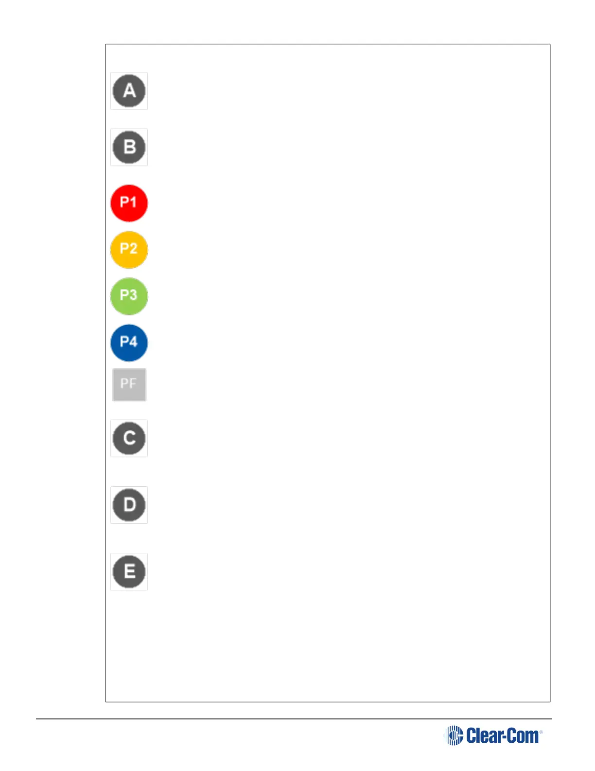
Example 4-Channel analog Main Station (MS-704 shown).
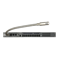
HMS-4X Main Station (digital Main Station).
Partyline Channel 1
Partyline Channel 2
Partyline Channel 3
Partyline Channel 4
Program Feed
Note: The program is always a participant within a Channel and cannot exist outside of
a Channel
.
In a traditional analog Partyline system, one cable is dedicated to each Partyline
Channel. This can make it more difficult to build redundancy or spare capacity into the
installation (owing to the number of connectors / cables dedicated to the delivery of
Channels).
In the HelixNet system, one cable can carry multiple Channels. Because one cable can
carry all Channels, the second connector for each line can either be used for
redundancy (flybacks) or for future extensions / changes to the cabling topology
(layout).
Example analog Partyline devices including RS-701 beltpacks. Analog beltpacks must
be re-cabled to use alternative Channels, requiring the physical re-location of cabling
for new configurations.
To aid switching, Clear-Com sells additional switching equipment (the SB-704 and
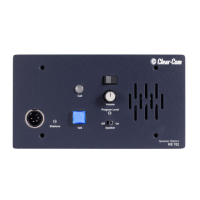
RCS-2700 devices). The RS-702 (6-pin XLR) beltpack requires the YC-36 splitter /
combiner to combine 2 Channels into a 6-pin configuration, and multi-conductor
cables.
The RS-703 (3-pin XLR) beltpack requires a TWC-701 device to combine 2 Clear-
Com Channels in a single twisted pair.
Page 55
 Loading...