HelixNet | User Guide
Key to analog and digital cabling comparison diagram
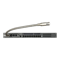
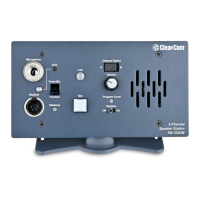
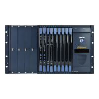
Example digital Partyline devices including beltpacks. Digital beltpacks can support any
of the Partyline Channels (plus Program Feed) whenever they are physically located
on the system.
New configurations of beltpacks and Channels can be deployed without the physical
relocation of assets.
Note: The capabilities of different cable types may impact how far away beltpacks can be
placed from the Main Station, and the topologies you use. For more information about
cabling, see Cabling reference.
3.1.2 Topologies
HelixNet Partyline can be deployed using a wide range of topologies, both complex and
straightforward. The following table describes three standard types of topology:
Topology Description
Daisy-
chain
In a daisy-chain topology, the Main Station is connected to the first unit. The units are
then connected in a series, using the pass-through connector on the back / rear of the
device to pass on the connection. No termination is required. HXII-BP-X4 beltpacks
require a passive Y splitter for daisy chaining.
Daisy-chains can be either linear or loop back to the Main Station to form a ring for
redundancy.
Star In a star topology, the Main Station is connected to a passive (Y) splitter such as an
XLR Bulkhead or Mult-box. The units are then connected to the splitter point-to-point.
Tree A tree topology is a more complex version of the star topology, using serially connected
passive ( Y ) splitters. The units are connected to each splitter point-to-point (forming a
branch of the tree).
Page 56
 Loading...


