Wiring diagram
GENERAL
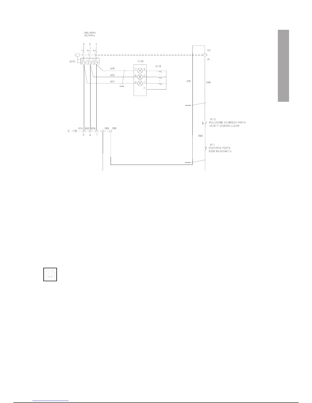
The kit for the IVECO option includes a blinker, a microswitch and a keylock selector switch.
The function of the blinker (H120) is to display the power supply state of the electric equipment within the
controller.
Therefore it must be connected just after the main isolator switch and placed in such a position as to be
clearly visible when the controller doors are open.
The blinker is connected to the three-phase line, without neutral earth wire, to signal for the harmful condition
which is actual when the main voltage is applied; such condition is signalled by means of three red blinking
lamps of the discharge type.
The blinker, connected as above mentioned, signals the mesh connection of three or two
phases by lighting up the corresponding lamp.
The mesh connection of one phase only is not signalled (all the lamps are off).
The blinker is installed together with a limit switch (S110) with three normally closed (N.C.) contacts, which
makes the blinker turn on when the cabinet doors are opened
When the door of the controller is opened, the single-throw limit switch (S111), having one normally-closed
(N.C.) contact, makes the main switch trip automatically by powering up the coil (D1, D2).
The keylock selector switch (S112), installed on the controller door, permits to cut out the automatic tripping
of the switch.
C3G Plus OPERATOR INTERFACE
05/1199 3-71
C3G Plus KIT IVECO