CIRCUIT DIAGRAMS
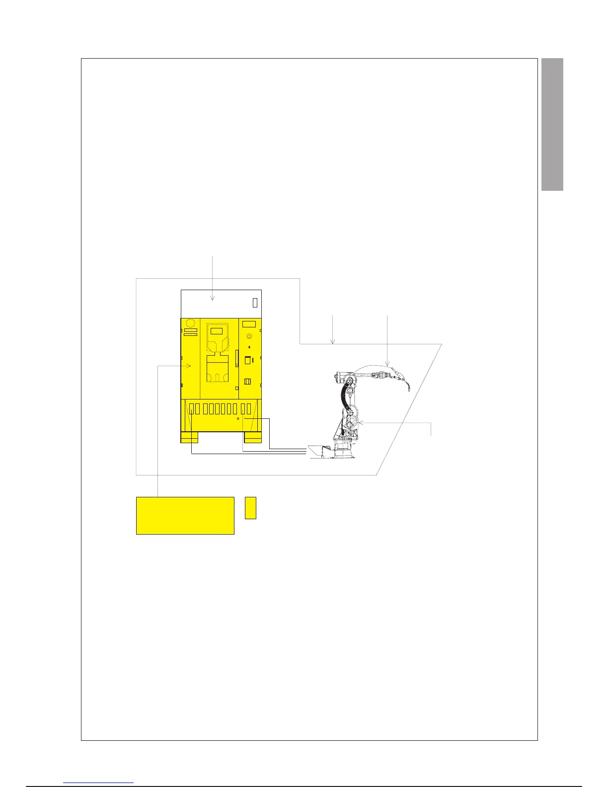
The controller circuit diagrams are gathered in a folder called CONTROL SYSTEM CIRCUIT DIAGRAM
which is provided with this Operations and Maintenance manual.
The wiring diagrams concerning: Application Box, Robot, fittings/cell outside the controller are provided with
the documentation for the robot system, in special folders, separate from the controller circuit diagrams.
EXAMPLE
C3G Plus MAINTENANCE
01/0498 7-41
CIRCUIT DIAGRAMS
SCHEMI ELETTRICI
APPLICATION BOX
SCHEMI
ELETTRICI
CELLA
SCHEMI ELETTRICI
ALLESTIMENTI/
ATTREZZATURE
ROBOT
CIRCUIT
DIAGRAM
CONTROL SYSTEM
CIRCUIT DIAGRAM
APPLICATION BOX
CIRCUIT DIAGRAMS
CELL
CIRCUIT
DIAGRAMS
FITTINGS/EQUIPMENT
CIRCUIT DIAGRAMS
ROBOT
CIRCUIT
DIAGRAMS
Provided with C3G
Plus Operations and Maintenance manual