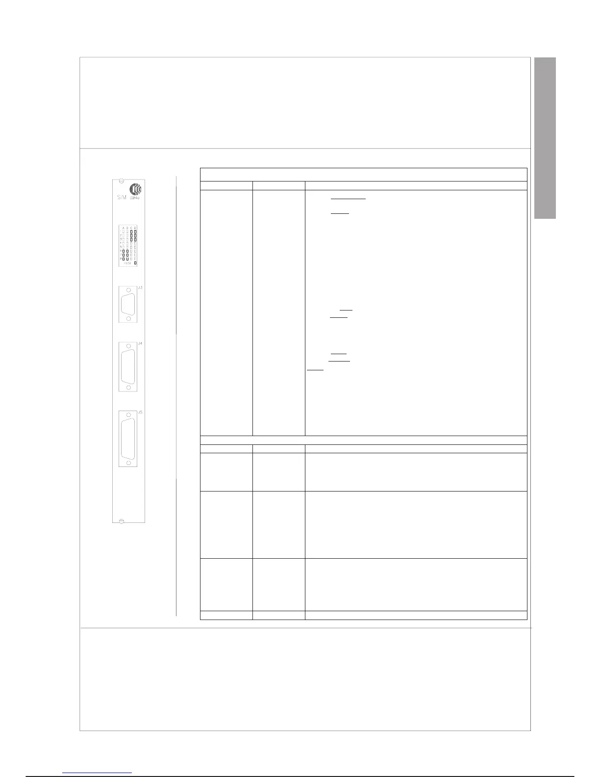
C3G-SIM SYSTEM INTERLOCK MODULE
System I/O module which interfaces certain control unit internal assemblies; it manages the I/O to the transfer and implements part of
the safety circuits with relay logic.
The outputs to the transfer are protected by fuse with specific indication on the monitoring system in the event of breakage.
It is a VME bus slave module.
FRONT PANEL
MEANING
LED Colour Description
A1
A2
A3
A4
A5
A6
A7
A8
B1
B2
RED
RED
RED
RED
RED
RED
RED
RED
RED
RED
Remote DRIVE ON (INP 9)
Remote DRIVE OFF
(INP 10)
Remote START (INP 11)
Remote HOLD
(INP 12)
Remote U1 (INP 13)
Remote U2 (INP 14)
Remote U3 (INP 15)
Remote U4 (INP 16)
Spare external input (INP 8)
External safety / External emerg. stop (INP4)
B3
B4
B5
B6
B7
B8
C1
C2
C3
C4
C5
C6
C7
C8
RED
RED
RED
RED
RED
RED
RED
RED
RED
RED
RED
RED
RED
RED
Machine 1 alarm (INP 17)
Machine 1 flange (INP 18)
Air pressure (INP 19)
Not used (INP 25)
Not used (INP 26)
Auto/Local (INP 27)
DRIVE ON/OFF
to remote (OUT 9)
START/HOLD
to remote (OUT 10)
U1 to remote (OUT 13)
U2 to remote (OUT 14)
U3 to remote (OUT 15)
U4 to remote (OUT 16)
Remote/Local
to remote (OUT 11)
Enable/Disable
teach to remote (OUT 12)
D1
D2
D3
D4
D5
D6
D7
D8
FUSE
RED
ROSSO
RED
RED
RED
RED
RED
RED
RED
Alarm
to remote (OUT 4)
DRIVE ON command (OUT 1)
DRIVE ON enable (OUT 2)
Spare external output (OUT 3)
Alarms inhibit (OUT 5)
Alarm (OUT 7)
System ON (OUT 8)
Low voltge during prog. (OUT 6)
Monitor fuse 1 (INP FUSE)
SIM Module connectors
Connector Pin no. Functions
J3 female 15 CONNECTOR WITH OPERATOR PANEL
Carries the following signals:
- EMERGENCY STOP (double channel)
- Programming terminal/EMC connected
- 24 Vdc supply to Operator Panel
J4 male 25 AC POWER DISTRIBUTION CONNECTOR
Carries the following signals:
- Commands to contactors and contactor status feed-back
- External EMERGENCY STOP
- Safety gate external emergency
- 24 Vdc fuse monitoring, machines and transfer
- Monitoring of correct operation of the power on and off
chain relays
- 24 Vdc supply for logic to SIM module relays
J5 male 50 EXTERNAL CONNECTION BOX CONNECTOR
Carries the following signals:
- Input from transfer
- Output to transfer
- Input and alarms from machine
- Servo Control CPU OK and Robot CPU OK
leading from the safety relays of the two modules
P1 96 VME BUS CONNECTOR
REPLACEMENTS
Specific cautions:
·
Comply with the “GENERAL RULES FOR MAINTENANCE” given in this chapter.
Special tools: unnecessary
C3G Plus MAINTENANCE
07/1200 7-47
LAYOUT
CONTROL UNIT C3G-SIM