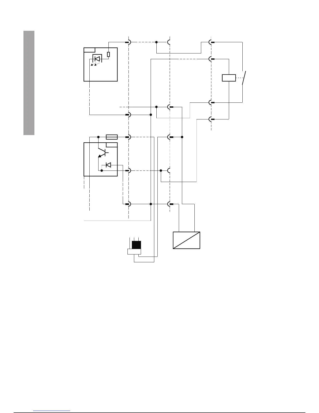
Example of I/O Connection with External 24 Vdc Power Supply
MACHINE LINE - ROBOT SIGNALS
For the connection of signals from the machine line to the robot it is possible to use the input channels con
-
nected directly from connector X30 (X30-2) to the connector on the robot and shown in the previous table.
The current/voltage limits of the inputs must never be exceeded.
CONNECTION OF ADDITIONAL I/O MODULES
The additional I/O modules inserted in the Control Unit (CU) rack have a front connector usually identified as
J3 which is connected by a harness and a 64-PIN HARTING connector located on the front panel of the con
-
troller, in the provisions reserved for additional connectors identified as X31 for the first module, X32 for the
second and so on in rising order.
INTEGRATION GUIDE C3G Plus
4-20 03/0499
INP1
X3/IOM
X30
A1
F1
AR
CC
C1
OUT1
CR
91
+
-
24 Vcc EXT
X90/ROBOT
T
B
C
H
0V(+24VccINT)
(IOM)
73
107
99
108
JP 200/SDB3
0V +24Vcc
1
2
3
parallel i/o basic c3g-iom