C3G-PWR3 POWER SUPPLY
This is the power supply of the modules in the Control Unit and it generates the output voltages needed to operate the modules and the
typical signals required by the specifications of VME standard. It has a recharging circuit for the Control Unit buffer battery.
It is inserted in the special slot at the left inside the Control Unit rack and its power rating is 185 W.
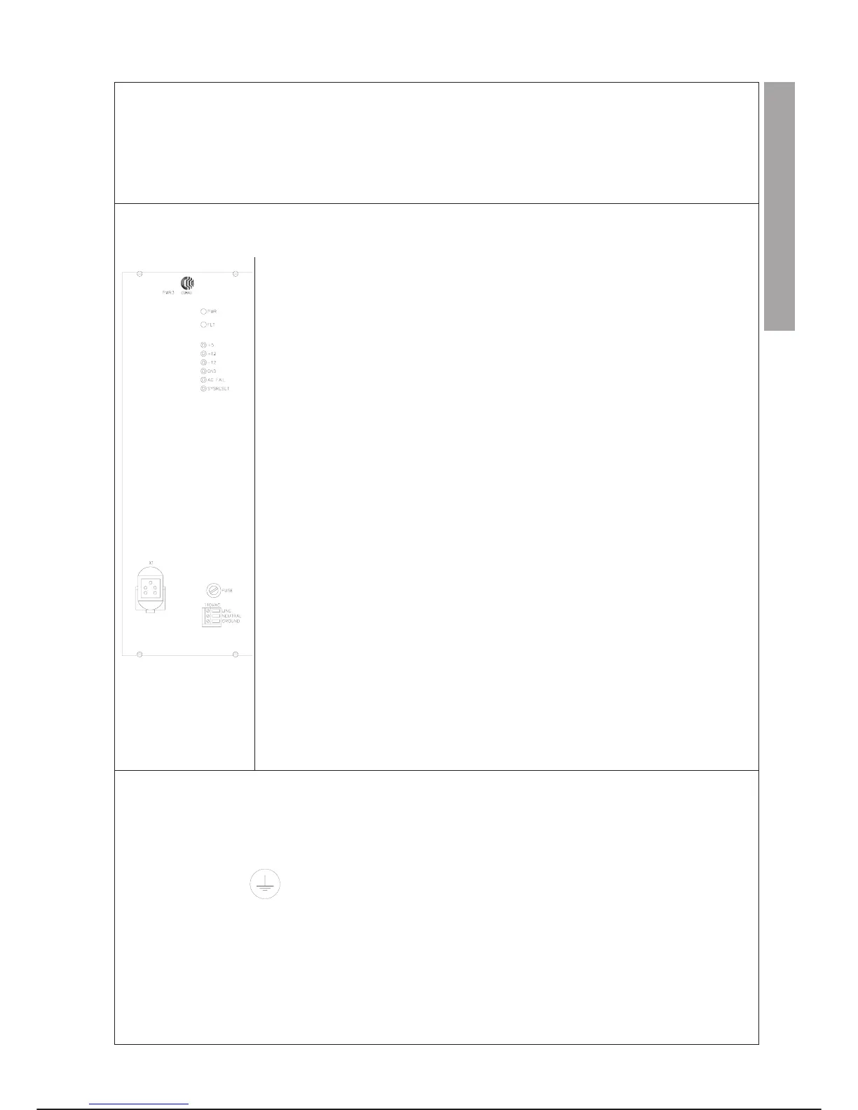
FRONT PANEL
MEANING
LED Colour Description
PWR GREEN When on it indicates that the system is correctly supplied and the presence
of the voltages and VME logic signals at the output. It is off when the FLT
led turns on.
FLT RED When on it indicates a fault status which derives from the cutting in of a
protection or from a mains supply failure of over 20 ms, i.e. the condition in
which all the power supply outputs are inhibited up to the removal and
subsequent return of the input voltage. If the mains voltage fails, it stays on
for the status memory storage time (a few seconds); within this time the
power can not be turned on again. When the FLT led lights up the PWR led
goes out.
Test Point of PWR1 module
Test point Colour Description
+ 5 V RED Makes it possible to check the presence of +5V at the power supply output
(measurement referring to black GND test point)
+12 V RED Makes it possible to check the presence of +12V at the power supply output
(measurement referring to black GND test point)
-12 V RED Makes it possible to check the presence of -12V at the power supply output
(measurement referring to black GND test point)
GND BLACK Reference test point for measurement on all the other test points
AC FAIL LIGHT BLUE Makes it possible to check the presence of the standard VME ACFAIL signal
(measurement referring to black GND test point)
SYSRESET LIGHT BLUE Makes it possible to check the presence of the standard VME SYSRESET
signal (measurement referring to black GND test point)
(FUSE - Power supply PWR1 protection fuse)
The checks on the test points must be carried out with instruments with a minimum input impedance of 1 MW.
PWR1 module connectors
Connector Pin no. Functions
X1 5 150 Vdc connection to module C3G-BKM
P1 96 VME BUS CONNECTOR
110 VAC 3 Connection with 110 Vac mains
terminal
PWR1 Module Fuses
FUSE PWR1 power supply module protection fuse
REPLACEMENTS
Specific cautions:
·
Comply with the “GENERAL RULES FOR MAINTENANCE” given in this chapter.
·
Connection to ground of the CONTROL UNIT is made through the GND terminal in the PWR3 module: it must always be
active.
·
Check correct clamping of connector X1.
Special tools: unnecessary
C3G Plus MAINTENANCE
07/1200 7-43
LAYOUT
CONTROL UNIT C3G-PWR3