C3G-IOM (16 INPUT/16 OUTPUT MODULE)
This is a slave module of the VME bus.
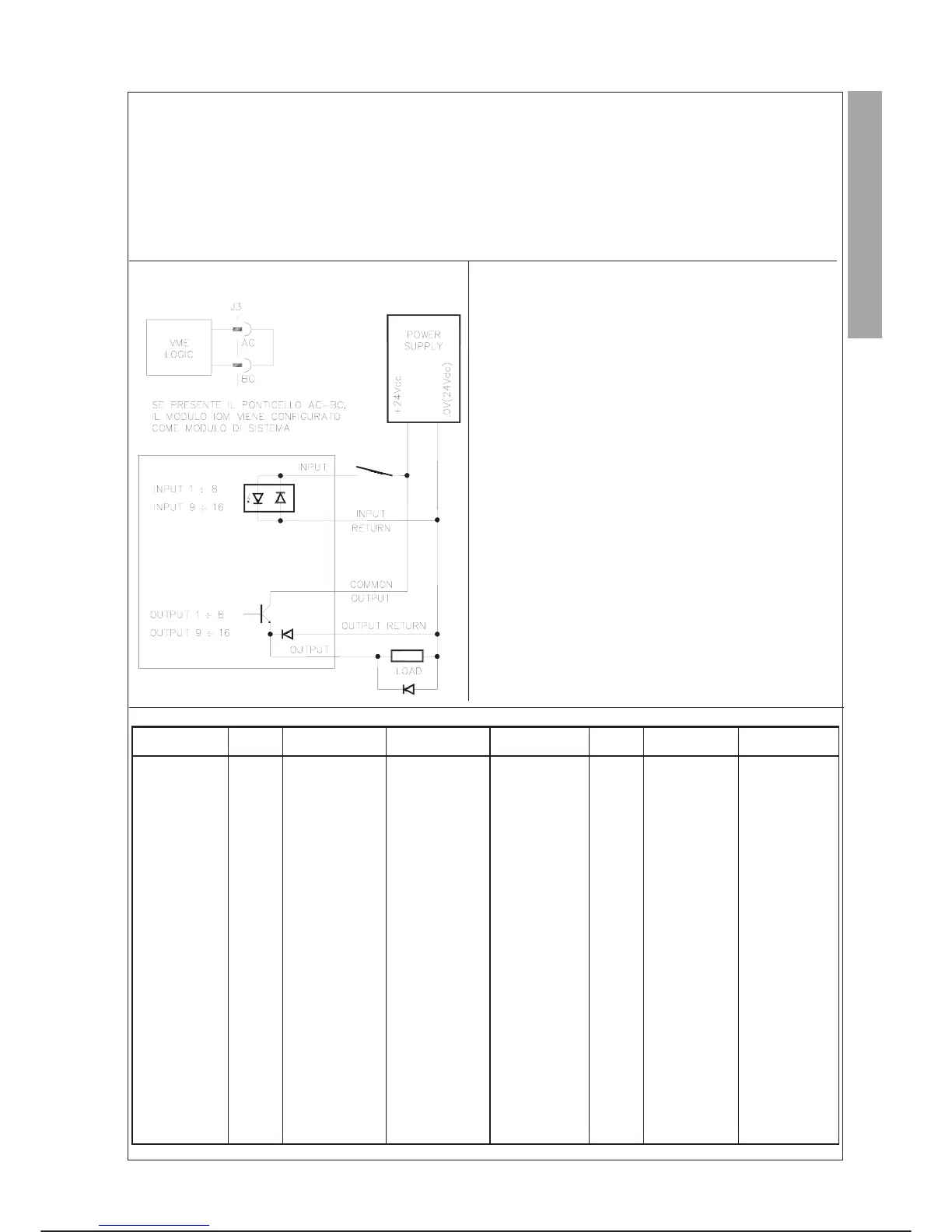
The module can be configured for C3G IOM user or C3G IOMs system I/O’s (special version); in this case it is recognised by the RBC
module and mapped in the area of I/O’s not available to the user and the function of each channel is pre-defined univocally.
It handles up to 16 Inputs and 16 Outputs. The outputs are protected by fuse with, in the event of breakage, specific monitoring indica
-
tion. When an input or output is activated the corresponding LED on the front panel lights up.
It may be added on the Control Unit rack starting from the first external slot at the right of the base configuration modules.
TECHNICAL CHARACTERISTICS
INPUT
Number of inputs
16
Number of common returns (0 V)
2
Type of input
IEC Type 1
Input voltage for channel activation
14 to 36 Vdc
Input voltage for channel deactivation
0to5Vdc
Input current with channel activated
2to15mA
Input current with channel not activated
0.5 mA
OUTPUT
Number of outputs
16
Number of common returns (24 Vdc)
2
Fuses (one for each common return)
5 A/250 V Normal Blow
Type of output
transistor
Operating voltage
4.5 to 36 Vdc
Maximum output current with all channels active
0.5A@ta=25°C
0.4A@ta=45°C
SIGNAL ALLOCATION
SIGNAL
RED
LED
CONN. J3 PIN
(MOD. FRONT)
CONN. X3X PIN
(CABINET BASE)
SIGNAL
RED
LED
CONN. J3 PIN
(MOD. FRONT)
CONN. X3X PIN
(CABINET BASE)
IOM MOD.
SYSTEM CONFIG.
–AC –
OUTPUT 1
C1 C1 C1
IOM MOD.
SYSTEM CONFIG.
–BC –
OUTPUT 2
C2 C2 C2
INPUT 1
A1 A1 A1
OUTPUT 3
C3 C3 C3
INPUT 2
A2 A2 A2
OUTPUT 4
C4 C4 C4
INPUT 3
A3 A3 A3
OUTPUT 5
C5 C5 C5
INPUT 4
A4 A4 A4
OUTPUT 6
C6 C6 C6
INPUT 5
A5 A5 A5
OUTPUT 7
C7 C7 C7
INPUT 6
A6 A6 A6
OUTPUT 8
C8 C8 C8
INPUT 7
A7 A7 A7
OUTPUT 9
D1 D1 D1
INPUT 8
A8 A8 A8
OUTPUT 10
D2 D2 D2
INPUT 9
B1 B1 B1
OUTPUT 11
D3 D3 D3
INPUT 10
B2 B2 B2
OUTPUT 12
D4 D4 D4
INPUT 11
B3 B3 B3
OUTPUT 13
D5 D5 D5
INPUT 12
B4 B4 B4
OUTPUT 14
D6 D6 D6
INPUT 13
B5 B5 B5
OUTPUT 15
D7 D7 D7
INPUT 14
B6 B6 B6
OUTPUT 16
D8 D8 D8
INPUT 15
B7 B7 B7
OUT 1 ¸ 8 COM.
– CC C10
INPUT 16
B8 B8 B8
OUT 9 ¸ 16 COM.
– DC D10
INPUT 1 ¸ 8 RET.
– AR A12
OUT 1 ¸ 8 RIT.
– CR C12
INPUT 9 ¸ 16 RET.
– BR B12
OUT 9 ¸ 16 RIT.
– DR D12
OUT FUSES
FUSE – –
C3G Plus INTEGRATION GUIDE
01/0498 4-23
parallel i/o C3G-IOM
EXAMPLE OF CONNECTION