C3G-ADM 2 ANALOG OUT-8 DC INP-8DCOUT
VME Input/Output module compatible with slave type interface. It comprises 2 analogue output channels, 8 24 VDC digital input chan
-
nels and 8 24 VDC digital output channels with signalling by LEDs on the front panel when the channels are active. It may be added on
the Control Unit rack starting from the first free slot on the right of the basic configuration modules.
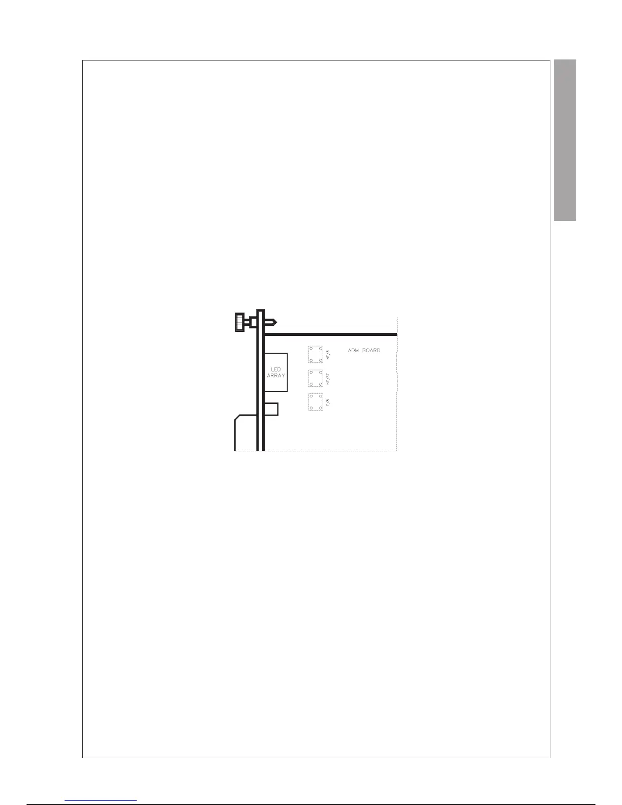
POWER FAILURE ON OPTOISOLATED ANALOGUE OUTPUTS POWER SUPPLY VOLTAGE
On the ADM module, detection of the presence of the power supply voltage (24 Vdc) of the optoisolated analogue section is provided.
Suitably positioning a 3-position jumper block it is possible to choose one of the following indications:
·
position NF/8 (Signalling level: NONE)
-
The lack of external voltage is not detected.
·
position F/8 (Signalling level: SYSTEM)
-
The lack of external voltage causes activation (1) of the FAIL bit in the status register on the VME Bus and consequently a fatal
alarm that blocks the system.
·
position NF/ST (Signalling level: USER)
-
In this case input no. 8 is dedicated to signalling the power failure at user level and therefore subtracted from normal use; any
external use of channel 8 (connection on connector J3) is ignored. The system user can programme the effect of this alarm via
PDL2.
TECHNICAL SPECIFICATIONS
DIGITAL INPUTS DIGITAL OUTPUTS ANALOGUE OUTPUTS
Number of inputs
8
Number of common earths
1
Input voltages for channel activation
14.0 to 36.0 Vdc
Input voltage for channel deactivation
0.0 to 5.0 Vdc
Input current with channel activated
2.0 to 15 mA
Maximum input current with channel
not activated
0.5 mA
Protection against polarity inversion
Through diode
Number of outputs
8
Number of common outputs
1
Fuse (on common return)
8A 125 V Normal Blow 5x20
Type of output
Transistor
Operating voltage
4.5 to 36 Vdc
Maximum output current with channel not
activated
0.2 mA
Maximum voltage drop with channel active
2.2 Vdc
Maximum output current
CHANNELS ACTIVE CURRENT CURRENT
SIMULTANEOUSLY @ ta = 25°C @ ta =
45°C
4 2 A 1,5 A
8 1 A 0,5 A
Protection against transient through diode
Number of outputs
2
Type of output
Single-ended Optoisolated
Voltage
from0Vto+10V
Load resistance
Output in voltage: minimum 2000 W
Resolution
11 bit
Precision
±0.5% full scale value at 25°C
±0.7% full scale value at 60°C
Reply time for all output channels
10 ms maximum
Settling time
1 ms max.
Short-circuit effects
No damage due to permanent short circuit
Insulation voltage
1500 V
ms
The analogue outputs are not isolated from one another
Power supply voltage of the optoisolated section
External 24 Vdc ± 20% (absorption max. 0.05 A)
Fuse on power supply of the optoisolated section
1 A 125 V Normal Blow 5x20
“Power fail” signal on power supply of the
optoisolated section for external voltage <19,5 V
C3G Plus INTEGRATION GUIDE
01/0498 4-31
parallel i/o C3G-ADM