C3G-RBC2 ROBOT CPU
At cell level this is the central unit for operating system management and interpretation of the user programmes, trajectories, interfaces.
It acts as PLC for the local I/O. It contains a shared memory area accessible from both board and VME bus; if inserted in the first slot it
also works as “system controller” of the VME bus.
It is connected to the operator interface via serial line, to the Personal Computer (option) and to the Floppy Disk Unit (option). It has a
parallel port for fast operating system loading.
The RAM storage installed on the module is supplied by a backup battery capable of ensuring data retention for at least 1000 consecu
-
tive hours; the board also has a high capacity condenser which makes it possible to remove the Control Unit module for maintenance
operations and/or installation without losing data for approx. 1 hour.
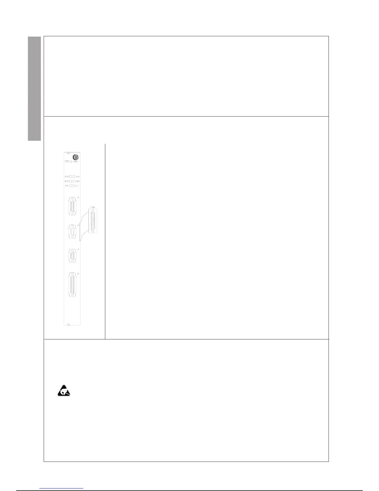
FRONT PANEL
MEANING
LED Colore Descrizione
BTB RED It turns on when the backup battery of the Control Unit is below a charge
level no longer sufficient to ensure data retention for the time foreseen. The
battery can be replaced without losing the data (see preventive
maintenance).
RUN GREEN It turns on at the end of the diagnostic tests run by the microprocessor if no
module operating faults have been detected.
WDG RED It turns on after cutting in of the watchdog circuit due to microprocessor fault.
BMS GREEN It turns on when the RBC module carries out the Master functions of the
VME Bus.
SYF RED It turns on when a fault has been detected at VME Bus or VME master
board (SYSFAIL) level.
SFT RED It turns on when the safety chain relay is opened.
RBC Module Connectors
Connector Pin no. Functions
J3 female 25 FDU SERIAL LINE, serial line EIA RS232, RS422, with modem signals for
connection with Floppy Disk Unit (RS422) or with the Personal Computer
(RS232).
J4 male 9 SAFETY RELAY Contact available for safety chain. It is closed after the
diagnostic tests run at system power-up; it opens for cutting in of the
watchdog circuit or on microprocessor command
J5 female 9 Not connected.
J6 female 25 OPERATOR PANEL SERIAL LINES Serial lines and supplies connected
with:
- programming terminal (EIA RS422)
- alphanumeric keyboard (EIA RS422)
- User, line available (EIA RS232 or
RS422 with modem signals)
PAR: female 25 Parallel line for loading operating system
P1 male 96 VME BUS CONNECTOR
REPLACEMENTS
Specific cautions:
·
Comply with the “GENERAL RULES FOR MAINTENANCE” given in this chapter.
·
Remove/insert the module avoiding damaging the components fitted on it.
·
Before replacing the module save the RAM DISK contents(see paragraph SUBSEQUENT SYSTEM SOFTWARE LOADING WITH
SAME SOFTWARE VERSION - SYSTEM SOFTWARE of this chapter).
·
The module removed from the Control Unit rack can keep the data in storage for 1 hour.
·
If the module is replaced the operating system resident on it is lost and it is necessary to reload it after inserting the new module.
Special tools: unnecessary
MAINTENANCE C3G Plus
7-44 07/1200
LAYOUT
CONTROL UNIT C3G-RBC2