CONNECTION OF ANALOGUE OUTPUTS (2/2)
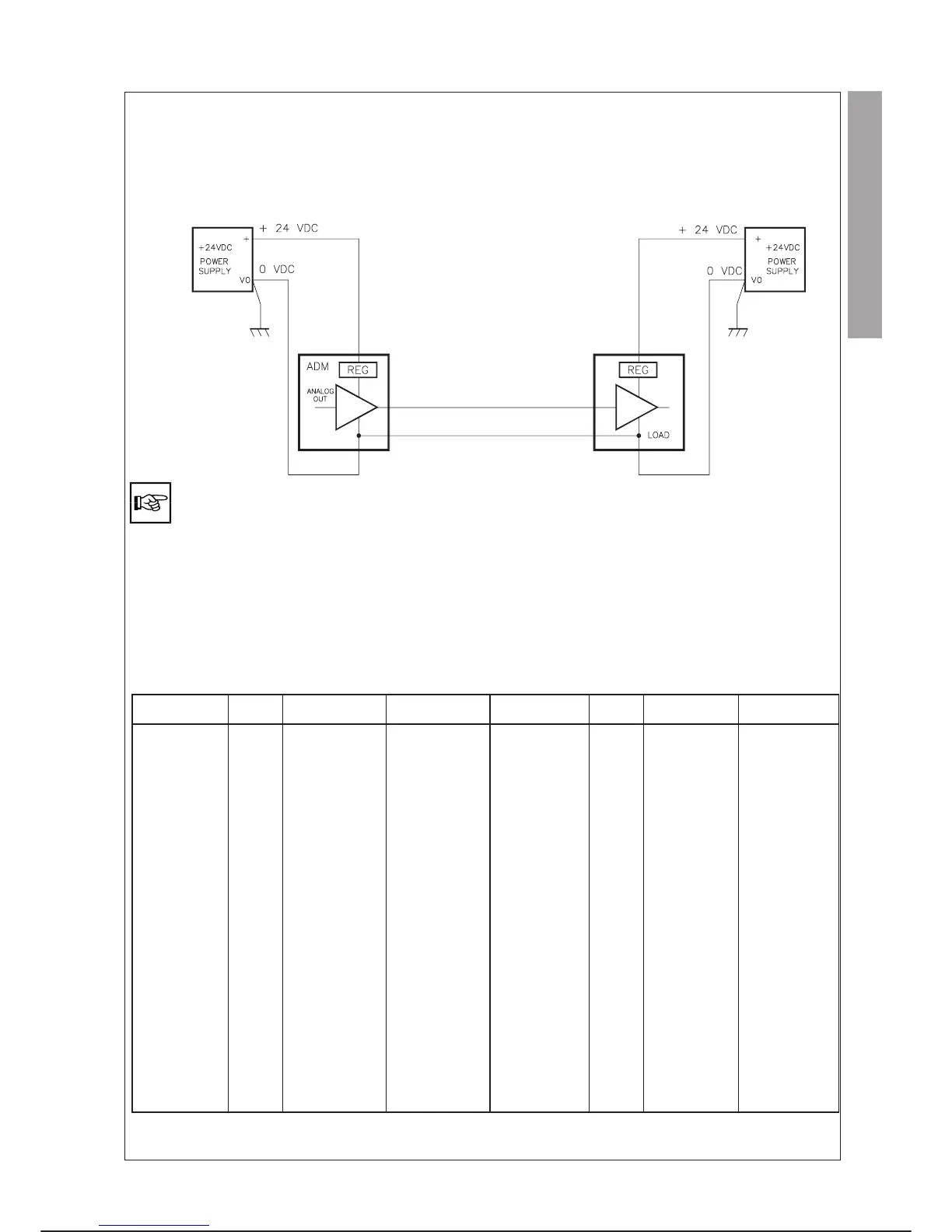
2. Separate power supply
This type of connection requires the use of two power supplies. The first connected to the optoisolated section of the ADM module and
the second to the load.
This solution is recommended when the load device requires high command signal precision. The 0 V must be earthed only on the
power supply connected to the load device.
The connection must be made only with a shielded cable or shielded twisted pair. The shield must be connected to
earth from the signal source side.
The cable used for the connection must be as short as possible.
Do not lay the cable close to high energy sources or in cable fairleads with other cables.
In the event of crossing other cables try to provide an intersection at right angles.
Do not lay the cable on surfaces subject to vibration.
Do not bend the cable with bending radii that are too small.
SIGNAL ALLOCATION
SIGNAL
RED
LED
CONN. J3 PIN
(MOD. FRONT)
CONN. X3X PIN
(CABINET BASE)
SIGNAL
RED
LED
CONN. J3 PIN
(MOD. FRONT)
CONN. X3X PIN
(CABINET BASE)
INPUT 1
A1 A1 A1
OUTPUT 1
C1 C1 C1
INPUT 2
A2 A2 A2
OUTPUT 2
C2 C2 C2
INPUT 3
A3 A3 A3
OUTPUT 3
C3 C3 C3
INPUT 4
A4 A4 A4
OUTPUT 4
C4 C4 C4
INPUT 5
B1 B1 B1
OUTPUT 5
D1 D1 D1
INPUT 6
B2 B2 B2
OUTPUT 6
D2 D2 D2
INPUT 7
B3 B3 B3
OUTPUT 7
D3 D3 D3
INPUT 8
B4 B4 B4
OUTPUT 8
D4 D4 D4
INP 1 ¸ 8 RET.
– AR A12
OUT. 1 ¸ 8 COM.
– CC C10
OUT. 1 ¸ 8 RET.
– CR C12
ANAL. OUT USER
POWER +24 Vdc
–C7 C7
ANAL. OUT USER
POWER 0 V (+24 Vdc)
–C8 C8
ANALOG OUT 1-
– A5 A16
ANALOG OUT 1+
– A6 A15
SHIELD ANAL.
OUTPUT 1
– A8 A14
ANAL. OUT 2-
– B7 B16
ANAL. OUT 2+
– B8 B15
SHIELD ANAL.
OUTPUT 2
– B5 B14
OUTPUT PROT.
FUSE
FUSE – –
C3G Plus INTEGRATION GUIDE
00/1097 4-33
parallel i/o C3G-ADM