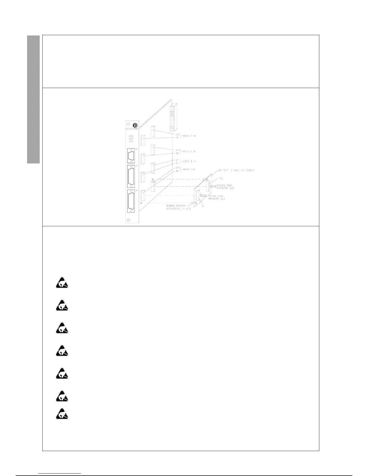
22’ DIFF. 2-AXIS I/O INTERFACE ANNEX
Each 22’ DIFF. 2-AXIS I/O INTERFACE annex reads the position and generates the current reference signals for two axes.
On a Servo Control CPU module up to four annexes can be installed, for managing a robot with a maximum of eight axes.
The annex connects to the SCC2 module through two connectors P1 (analogue signals) and P2 (digital signals).
LAYOUT
REPLACEMENTS
Specific cautions:
·
Comply with the “GENERAL RULES FOR MAINTENANCE” given in this chapter.
·
During ANNEX installation, replacement or removal operations the operating system may be lost.
·
Remove the SCC2 module carefully to avoid damaging the components assembled on both sides holding it by the fasten
-
ing screws.
·
Rest the SCC2 module on an insulating surface to avoid discharging the condenser which retains the operating system for
a maximum of 1 hour during operations of this type.
·
Insert the ANNEX completely on the connectors on the SCC2 module after inserting the annex screw spacer, pressing in
correspondence of the connectors and avoiding touching the components with the fingers.
·
Insert the SCC2 module in the special rack slot, taking care not to damage the components assembled on both faces, hold
-
ing it by the fastening screws.
·
Firmly tighten the fastening screws to ensure correct connection of the SCC2 module and rear connector, and to ensure
electrical continuity between the module and the chassis.
·
Insert the connectors on the front of the SCC2 module tightening the corresponding screws.
·
When replacing or removing the annex from the SCC2 module it is better NOT to remove the SCC2 module plastic spac
-
ers, but free the annex of the spacers lightly pressing the protruding parts of the spacers themselves.
Special tools: unnecessary
MAINTENANCE C3G Plus
7-46 07/1200
CONTROL UNIT I/O INT. ANNEX