C3G-SCC2 SERVO CONTROL CPU
The Servo Control CPU manages axes movement control in a machine receiving the trajectory targets from the RBC module, through
the VME bus in the master-slave mode and microinterpolating the trajectories themselves; it sends information about machine status
and any alarms to the RBC module, also through the VME bus.
The SCC2 module is interfaced with the machine for transmitting the resolver energising signal and resolver reading, and with the
Servo Amplifiers Unit 2 for transmitting current references.
The SCC2 module interface towards the Servo Amplifiers Unit is modular; in fact, on the SCC2 it is possible to install up to four AXIS I/O
annexes; each AXIS I/O annex reads the position and generates the current reference for two motors.
The Servo Control CPU manages up to 8 axes, also subdivided on two arms, as it possesses two interpolators. The RAM storage in
-
stalled on the SCC2 module also has an external backup battery supply capable of retaining data for at least 1000 consecutive hours;
there is also a condenser for powering the SCC2 module RAM for about one hour in the event of a power failure (also of the backup bat
-
tery) which makes it possible to remove the module from the Control Unit for any maintenance operations and/or installation of 22’
DIFF.2-AXIS I/O INTERFACE annex.
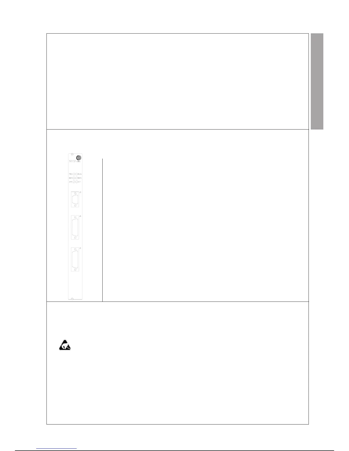
FRONT PANEL
MEANING
LED Colour Description
PRG GREEN When on indicates that the module is in the operating condition.
RUN GREEN Turns on at the end of the diagnostic tests performed by the microprocessor
if no module operating faults have been located.
WDG RED Turns on after the cutting in of the watchdog circuit for microprocessor
malfunctioning.
BMS GREEN This is on when the SCC module performs VME Bus Master functions.
SYF RED Turns on when an error is detected at VME bus or VME master board
(SYSFAIL) level.
SFT RED Turns on when the safety chain relay opens.
SCC Module connectors
Connector Pin no. Functions
J3 male 15 To resolvers of axes7-8
J4 male 50 To resolvers of axes 1 to 6 and serial line RS485 towards RPT
J5 female 50 Analogue signals to SAM modules; serial line RS485 to SAM modules;
safety chain
J6,J7,J8,J9 female 40 Connectors for analogue signals from and to AXIS I/O ANNEX
J6 axes 1-2
J7 axes 3-4
J8 axes 5-6
J9 axes 7-8
J10,J11 female 40 Connectors for digital signals J12, J13 from and to AXIS I/O ANNEX
J10 axes 1-2
J11 axes 3-4
J12 axes 5-6
J13 axes 7-8
P1 male 96 VME BUS CONNECTOR
REPLACEMENTS
Specific cautions:
·
Comply with the “GENERAL RULES FOR MAINTENANCE” given in this chapter.
·
Remove/insert the module avoiding damaging the components (annex) assembled on it.
·
Before replacing the module save the RAM DISK contents (see paragraph SUBSEQUENT SYSTEM SOFTWARE LOADING
WITH SAME SOFTWARE VERSION - SYSTEM SOFTWARE of this chapter).
·
The module removed from the Control Unit rack can keep the data in storage for 1 hour.
·
If the module is replaced the operating system resident on it is lost and it is necessary to reload it after inserting the new module.
·
The jumpers on the module must not be moved or removed.
Special tools: unnecessary
C3G Plus MAINTENANCE
07/1200 7-45
LAYOUT
CONTROL UNIT C3G-SCC2