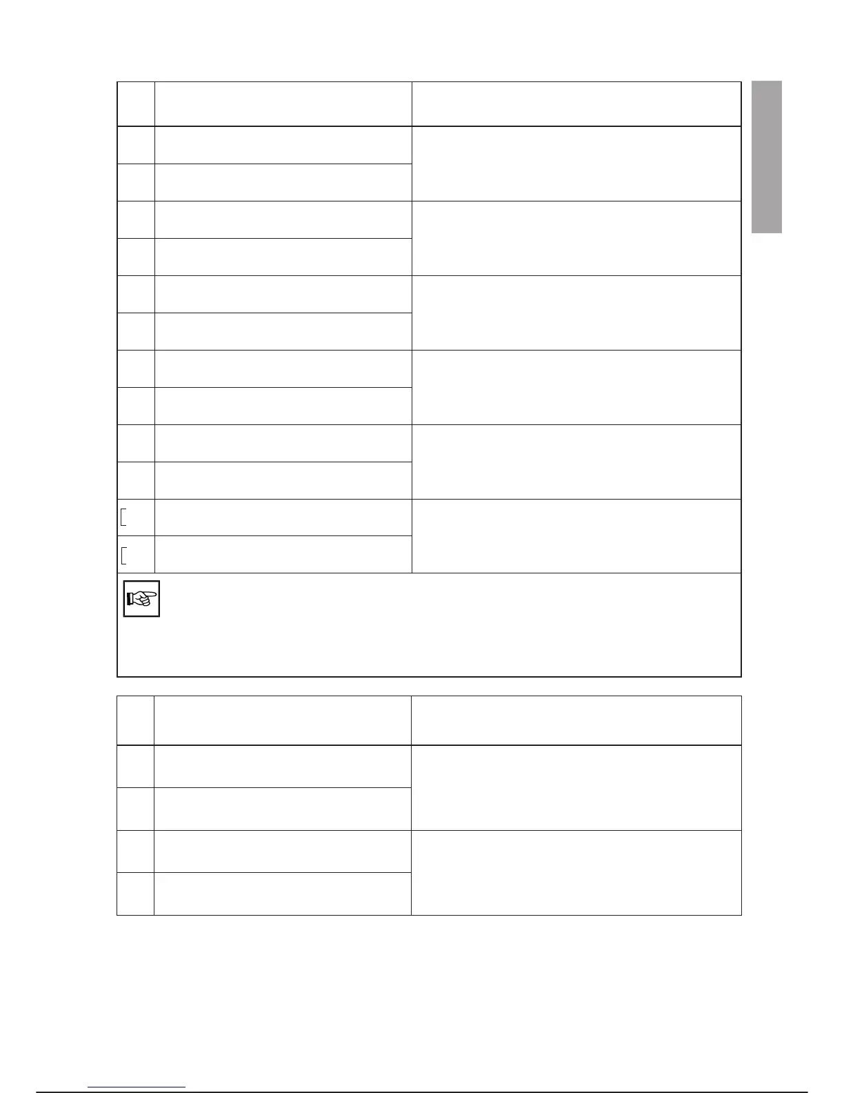
PIN
X30
SIGNALS DESCRIPTION
15
16
EXTERNAL SAFETY GATES CH1 INPUT
EXTERNAL SAFETY GATES CH1 OUTPUT
Safety signals to external equipment that must be used
to connect the safety gates and all devices that assure
operator safety during the work cycle.
17
18
EXTERNAL SAFETY GATES CH2 INPUT
EXTERNAL SAFETY GATES CH2 OUTPUT
33
34
EXTERNAL EMERG. STOP CH1 INPUT
EXTERNAL EMERG. STOP CH1 OUTPUT
Safety signals to external equipment that must be used
to connect a mushroom-head emergency button to in
-
terrupt the work cycle.
35
36
EXTERNAL EMERG. STOP CH2 INPUT
EXTERNAL EMERG. STOP CH2 OUTPUT
58
46
EXTERNAL SAFETY STOP CH1 OUTPUT
EXTERNAL SAFETY STOP CH1 INPUT
Safety signals to external equipment that can be used
for category 1 controlled stopping according to EN
60204-1 (if the C3G-SSM device is present on re
-
quest)
59
47
EXTERNAL SAFETY STOP CH2 OUTPUT
EXTERNAL SAFETY STOP CH2 INPUT
52
53
POWER CONTACTOR 1 INPUT
POWER CONTACTOR 1 OUTPUT
Auxiliary contacts of power contactors K101 and K102.
These are made available externally for connecting the
power supply to equipment or for detecting the status
of the power contactors.
55
56
POWER CONTACTOR 2 INPUT
POWER CONTACTOR 2 OUTPUT
6
24
SAFETY RELAY LOGIC CH1 INPUT
SAFETY RELAY LOGIC CH1 OUTPUT
Equipment supply contacts (Safety Relay Logic). Used
to connect the supply to the equipment through safety
relays.
66
68
SAFETY RELAY LOGIC CH2 INPUT
SAFETY RELAY LOGIC CH2 OUTPUT
48
50
INTERNAL +24 Vdc OUTPUT (x)
INTERNAL +24 Vdc INPUT (x)
Power connection to the safety circuits. Bridge (x) +24
Vdc, bridge (y) 0 V (+24 Vdc).
49
51
INTERNAL 0 V (+24 Vdc) OUTPUT (y)
INTERNAL 0 V (+24 Vdc) INPUT (y)
If the C3G-CSM (Controlled Stop Module) is installed on the controller, in AUTO LOCAL
and AUTO REMOTE states, an emergency stop and/or opening of the safety gates causes
controlled stopping of the robot (EN 60204-1), category 1 stop). In this way, power is cut off
(opening of the power contactor) after 1 second. In PROGR. programming status, the
power is cut off immediately (EN 60204-1, category 0 stop). These times must be taken into
account when installing the protective barriers in particular if light curtains are used.
PIN
X30-2
SIGNALS DESCRIPTION
52
53
POWER CONTACTOR 1 INPUT
POWER CONTACTOR 1 OUTPUT
Auxiliary contacts of power contactors K121 and K122.
These are made available externally for connecting the
power supply to equipment or for detecting the status
of the power contactors of machine 2.
55
56
POWER CONTACTOR 2 INPUT
POWER CONTACTOR 2 OUTPUT
6
24
MACHINE EXCLUSION 1 INPUT
MACHINE EXCLUSION 1 OUTPUT
Auxiliary contacts of relays K123 and K124. They are
made available externally for detecting the status of the
excluded machine.
66
68
MACHINE EXCLUSION 2 INPUT
MACHINE EXCLUSION 2 OUTPUT
C3G Plus INTEGRATION GUIDE
02/1198 4-3
SAFETY SIGNALS