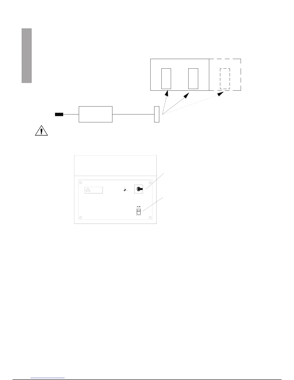
4. Connect the brake release device C3G-BRD in the following sequence:
a. connect the Harting connector of the device to connector X2, X2 EXT and X3 at the robot base;
b. connect the device socket to a 220 Vac power source outside the control unit.
Take the utmost care to work in the highest possible safety conditions in the operations we
are about to carry out.
5.
Release the brakes using the device and selecting the chosen axis (letting go of the release lever the
axis stops because the 24 Vdc is cut off).
6. Free the axis from the abnormal position.
7. Remove the C3G-BRD device.
8. Restore any damage suffered by the axis.
9. Carry out the TURN_SET operation (see chapter 2, step 11 of the installation procedure).
10. Restore normal system working conditions.
EMERGENCY PROCEDURES C3G Plus
6-4 08/0702
USE of C3G-BRD
X2 X2 EXT
220 Vca
C3G-BRD
X3
1-7
2-8
3
4
5
6
2
1
65
3
SELECTION OF AXIS TO
BE MOVED
BRAKE RELEASE