When using multiple APs in cascade or parallel from a BDA/MU/RU device, each AP must be addressed so
they can communicate properly with the BDA/MU/RU over RS485 protocol. A 4-position DIP Switch is
located on the internal PCB board and is used to set the address. When BDA/MU/RU is connected to one
AP, the address of the AP is set to 1. This is also the default address set from the factory. When two APs
are connected, the addresses are set to 1 and 2. A maximum of two APs can be connected in parallel. When
APs are being connected in cascade/series, each AP must be addressed according to its position in the
chain, with the 1
st
AP addressed as 1, and the 4
th
AP addressed as 4(MAX of 4 in cascade). The display of
FOU1~FOU4 in APV3-DAS is associated with the address of the alarm panel. For example, when both DIP
Switches are in the ON position, the address of the alarm panel is 4, and the FOU4 light for that APV3-DAS
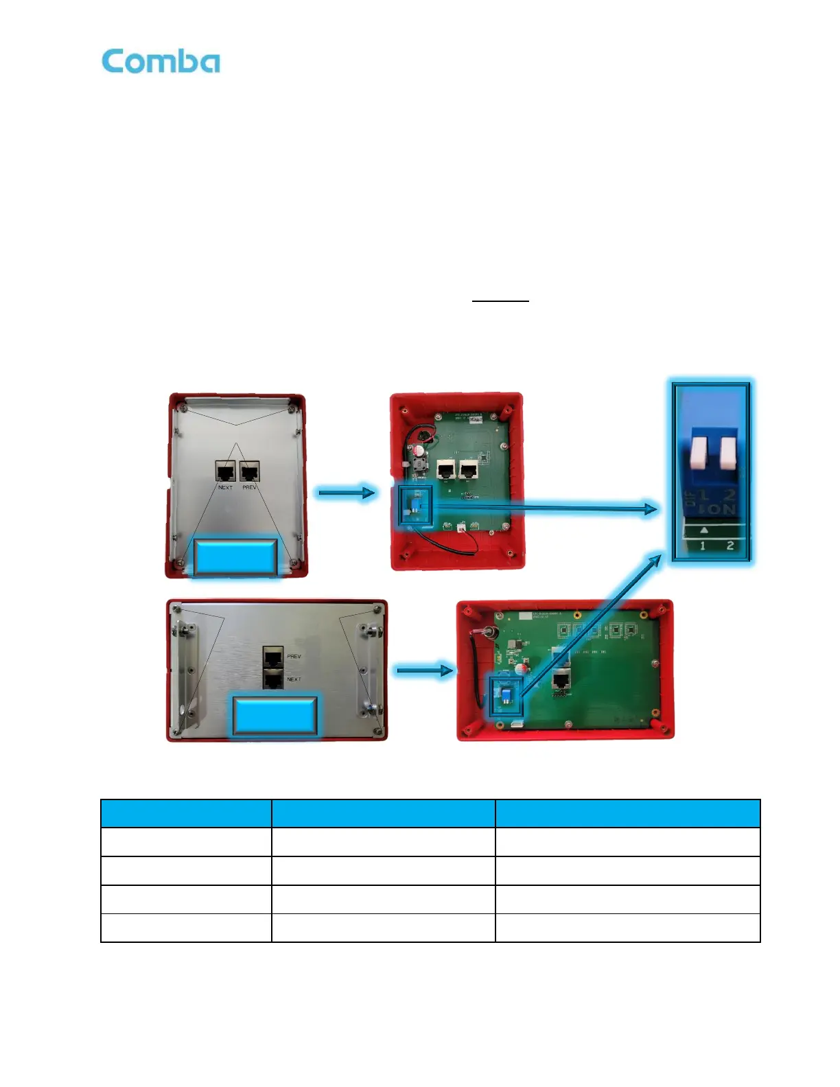
will illuminate, indicating that the panel displays an alarm for RUs connected to FOU4. Refer to Figure 79
and Table 9 below.
Use the below instructions to change the address of a V3 AP BEFORE installing:
• Lay the V3 AP down on its face. Remove the mounting bracket if it is attached.
• Remove the (4) Philips head screws holding the backplate in place. Remove the backplate.
• Change the address on the DIP switch accordingly. Refer to the following table for guidance.
• Reinstall the backplate.
Figure 79: V3 AP - Address Switch Setting
Table 9: V3 AP - Address Switch Setting
 Loading...